
Fluid / Hydrodynamic Couplings
Hydrodynamic power transmission, soft start, selection & replacement guide.
Industrial Fluid Couplings
Fluid couplings are hydrodynamic power-transmission devices used to provide smooth acceleration, controlled starting torque, drivetrain protection and vibration/shock decoupling. Unlike a conventional mechanical flexible coupling, torque is transmitted through the kinetic energy of a working fluid rather than through direct mechanical contact between the primary and secondary impellers.
MECHATRIC supports constant-fill, delay-chamber and variable/fill-controlled hydrodynamic coupling applications, including new selection, starting-duty review, technical cross-reference, retrofit evaluation and RFQ preparation.
Fluid Coupling Families
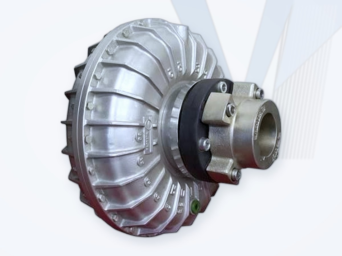
Westcar ROTOFLUID
Constant-fill fluid couplings (ROTOFLUID / ROTOFLUID-CA) for soft starting of conveyors, crushers, mills and general heavy-duty drives.
View Product →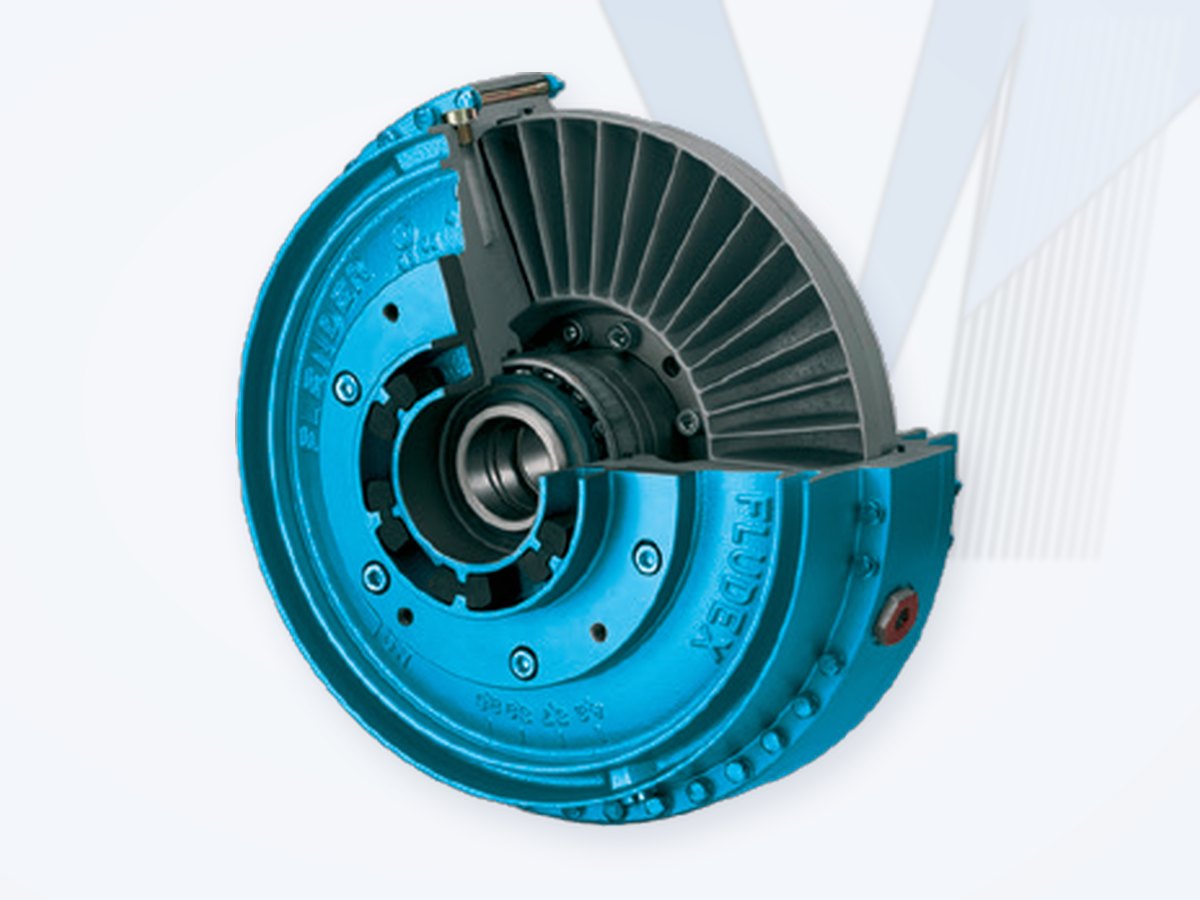
FLENDER FLUDEX
Constant-fill hydrodynamic couplings for soft starting, torque limitation, overload protection and vibration/shock decoupling.
Request a Quote →Voith Fluid Couplings
Constant-fill, delay-chamber and variable-speed / fill-controlled hydrodynamic couplings - reference family for engineering comparison.
Request a Quote →Transfluid Fluid Couplings
Constant-fill (K-series) and variable-fill fluid coupling families - reference family for engineering comparison.
Request a Quote →What is a fluid coupling?
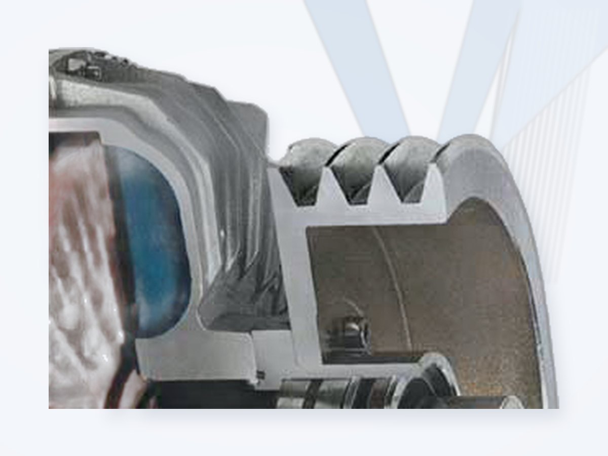
A fluid coupling - also called a hydrodynamic or hydraulic coupling - normally contains two bladed rotating elements facing each other in a sealed working chamber: a pump impeller connected to the driver and a turbine impeller connected to the driven machine. The pump imparts kinetic energy to the working fluid; circulating fluid transfers momentum to the turbine and produces output torque. This is the hydrodynamic principle commonly associated with Hermann Föttinger.
There is no positive mechanical torque-transmitting connection between the pump and turbine. A speed difference between input and output - slip - is necessary for torque transmission. At steady rated duty, a correctly selected constant-fill coupling normally operates with relatively small slip; during acceleration or overload, slip increases and the resulting energy is converted into heat.
How a Fluid Coupling Works
As the driver accelerates the pump impeller, centrifugal action establishes circulation in the working fluid. Fluid leaving the pump transfers momentum to the turbine and returns toward the pump, forming a toroidal flow path. The transmitted torque, starting characteristic, running slip and heat generation depend on coupling geometry, input speed, fluid filling and the driven-machine load characteristic.
Slip power becomes heat. Starting energy, acceleration time, starts per hour, overload duration, ambient conditions and thermal protection are as important as nominal motor power.
Key Engineering Benefits
- Soft and controlled acceleration - progressively accelerates the load instead of an abrupt mechanical start.
- Starting-torque limitation - reduces peak torque on belts, chains, gearboxes, shafts and driven machinery.
- High-inertia starting of conveyors, crushers, mills and similar loads when correctly thermally sized.
- Shock and torsional-vibration decoupling through hydrodynamic separation.
- Overload protection - increasing slip limits torque transfer; thermal protection adds a protective response.
- Contact-free hydrodynamic torque transfer between pump and turbine.
- Speed control in variable-fill systems over an application-dependent range.
Main Fluid Coupling Concepts
| Coupling concept | Function / characteristic | Typical applications |
|---|---|---|
| Constant-fill | Fixed fluid quantity establishes starting and running behavior; robust soft-start and protection solution. | Conveyors, crushers, mills, elevators, mixers and general heavy-duty drives |
| Constant-fill with delay / pre-chamber | Controls fluid transfer into the working circuit during acceleration to reduce or shape starting torque. | High-inertia conveyors, crushers and difficult loaded starts |
| Dynamic re-filling / special constant-fill | Internal fluid management maintains controlled starting behavior during extended acceleration. | Long-start centrifugal loads and selected fan/mill duties |
| Variable-fill / fill-controlled | Working-circuit fill is adjusted during operation for controlled torque and, depending on load, stepless output-speed control. | Large pumps, fans, compressors and process drives |
| Pulley / belt-drive arrangement | Integrates the fluid coupling with a belt-driven layout. | Fans, crushers, conveyors and compact industrial drives |
| Special / monitored designs | Thermal monitoring, fusible devices, special fluids, water operation or hazardous-area configurations. | High-duty, monitored or safety-sensitive applications |
Typical Applications & Industries
Mining & Cement: belt/apron conveyors, bucket elevators, crushers, tube/vertical mills, rotary kilns, roller presses and separators. Bulk Material Handling: long conveyors and high-inertia transport systems. Oil, Gas & Process: selected pumps, fans, compressors, mixers and process drives. Power Generation: fans, pumps, air condensers, cooling systems and auxiliary drives. Pulp & Paper, Water & Wastewater (aerators, water-screw drives) and Food, Sugar & Process (mixers, reactors, extraction systems, cane mills).
Fluid Coupling Selection - Engineering Method
Fluid couplings are selected primarily from the complete power-speed-load-starting-thermal duty, not from shaft diameter alone. Manufacturer performance curves and thermal limits for the exact series control final selection.
| Step | Engineering check | Required information |
|---|---|---|
| 1 | Identify driver | Motor/engine type, rated power, input speed, starting method, motor torque/current capability. |
| 2 | Identify driven machine | Conveyor, crusher, mill, pump, fan, mixer, etc.; load torque versus speed and operating duty. |
| 3 | Define breakaway and inertia | Breakaway torque, driven inertia J or WR2, loaded/unloaded start and target acceleration time. |
| 4 | Define start / overload duty | Starts per hour, restart conditions, reversing, stall/overload duration and duty cycle. |
| 5 | Choose coupling concept | Constant-fill, delay/pre-chamber, dynamic re-filling or variable/fill-controlled system. |
| 6 | Select preliminary size | Use the manufacturer's power-speed and starting/performance data for the exact application. |
| 7 | Optimize approved filling | Fluid quantity influences starting torque, acceleration, slip and heat; use only approved values. |
| 8 | Perform thermal check | Start energy, slip heat, acceleration time, starts/hour, ambient temperature and heat dissipation. |
| 9 | Check mechanical interface | Shafts, bores, keyways, fits, orientation, pulley/brake arrangement, envelope and access. |
| 10 | Specify protection / environment | Fusible plug, thermal switch/electronic monitoring, hazardous area, working fluid and special environment. |
Slip, Efficiency & Thermal Duty
Slip is essential to hydrodynamic operation: Slip (%) = (Input Speed - Output Speed) / Input Speed x 100. For a simple fluid coupling, the speed loss associated with slip also represents energy dissipated as heat, so operating slip directly influences efficiency and thermal loading.
There is no universal normal-slip value for all fluid couplings. FLENDER states approximately 2% operating slip at nominal load for the FLUDEX family, while Transfluid states that standard-duty slip for its K-series constant-fill couplings ranges approximately from 1.5% in larger-power applications to 6% in smaller-power applications. Final expectations must come from the exact series, size, filling and duty.
Starting Characteristic & Fluid Filling
For constant-fill couplings, filling quantity is an engineering setting rather than a generic consumable quantity. Changing the approved fill level changes starting torque, acceleration time, running slip and heat. Delay chambers and other internal filling-control arrangements can further shape torque build-up during acceleration.
Variable-fill systems change the working-circuit fill during operation, allowing controlled torque transfer and, where the driven-load characteristic permits, stepless output-speed regulation. They require selection of the complete coupling, oil system, controls and thermal package.
Thermal Protection & Monitoring
Repeated starts, prolonged acceleration, overload or stall can generate damaging heat. Depending on the coupling family, protection may include fusible safety plugs, thermal switches, non-contact temperature/operating monitoring or control-system instrumentation. The protective philosophy must match the exact coupling and machine risk.
A fusible plug is not a substitute for correct thermal sizing. The coupling is first selected for the required start/overload duty; protective devices are then configured according to the manufacturer's instructions.
Selecting for Belt Conveyors
- Loaded or unloaded start - does the conveyor routinely start with material on the belt?
- Belt length and elasticity - avoid excessive transient belt tension during acceleration.
- Inclination and breakaway torque - may involve backstop or brake requirements.
- Drive arrangement - motor, fluid coupling, gearbox, number of drives, pulleys, brake/backstop.
- Acceleration target - acceptable acceleration time and torque build-up.
- Starts and restarts - starts per hour, hot restart and restart after an aborted start.
- Manufacturer curves - validate delay-chamber or controlled-start configurations against the selected manufacturer's curves.
Crushers, Mills & High-Inertia Machines
- Breakaway and peak torque and transient shock loads.
- Reflected inertia as J, GD2 or WR2, including the effect of gearing.
- Motor capability - starting method, allowable current, accelerating torque, voltage/frequency.
- Energy per start - prolonged slip converts energy to heat and can govern size.
- Jam / overload condition and the required protective response.
- Restart philosophy - cold start, hot restart and minimum cooling interval.
- Thermal verification - a larger coupling, modified filling or controlled-start configuration may be required.
How to Select an Equivalent or Replacement Fluid Coupling
A replacement fluid coupling must reproduce the required hydrodynamic starting and running behavior as well as fit the mechanical installation. Matching motor power, nominal diameter or shaft bore alone is insufficient.
| Parameter | Why it matters |
|---|---|
| Driver power and input speed | Defines the basic hydrodynamic operating point. |
| Driven-machine load curve | Conveyor, crusher, pump and fan duties have different torque-speed characteristics. |
| Breakaway / starting torque | Determines whether the load can start without excessive drivetrain stress. |
| Driven inertia and acceleration time | Controls start energy and thermal loading. |
| Starts/hour and duty cycle | Repeated starts can overheat a coupling adequate for steady running. |
| Required starting characteristic | Geometry, fill, delay chamber and control strategy determine torque build-up. |
| Running slip / output speed | Influences process speed, efficiency and heat generation. |
| Maximum speed | Must remain within the exact mechanical rating. |
| Working fluid / filling | Directly affects performance and thermal behavior. |
| Shaft interface / dimensions | Required for mechanical interchangeability and installation. |
| Protection / controls | Thermal devices and control architecture must meet the machine safety philosophy. |
| Environment / certification | Ambient, hazardous area, orientation, contamination and special-fluid requirements. |
MECHATRIC Interchange Classification
- Direct Interchange - only when hydrodynamic performance, interfaces, dimensions, filling/protection and application duty have been verified.
- Dimensionally Compatible - mechanical envelope/interfaces are compatible, but hydrodynamic performance still requires verification.
- Functionally Equivalent - provides the required function but may differ in size, filling, starting curve, controls or installation.
- Engineering Review Required - candidate relationship identified but not approved as a public interchange.
For fluid couplings, dimensional compatibility alone never establishes hydrodynamic equivalence.
Technical Equivalency Sheet
For retrofit and cross-reference projects, MECHATRIC documents the comparison in a controlled Technical Equivalency Sheet: existing unit identification, application duty, hydrodynamic performance, mechanical interface, protection/controls, environment, a deviation register of every known difference, interchange status, and evidence/approval references.
Reference Fluid Coupling Families
Depending on duty, power, speed, start characteristic and control requirement, engineering comparison may involve established families such as FLENDER FLUDEX, Voith constant-fill and variable-speed fluid couplings, and Transfluid constant-fill and variable-fill systems. These references are used for technical comparison and are not automatically interchangeable.
- FLENDER FLUDEX: current FLENDER information lists nominal output from 1.2 kW to 2,500 kW across 15 sizes, a stated temperature range of -40 C to +50 C, and approximately 2% operating slip at nominal load, with soft starting, torque limitation, overload protection and vibration/shock decoupling as key functions.
- Voith: distinguishes constant-fill couplings, delay-chamber variants and variable-speed/fill-controlled hydrodynamic systems; variable-speed couplings adjust fill during operation for stepless speed control, with the range depending on the driven-load characteristic.
- Transfluid: distinguishes constant-fill and variable-fill families; for the K-series constant-fill design, slip is essential for torque transmission and standard-duty slip varies with application/power level.
Fluid Coupling vs. Mechanical Flexible Coupling
| Characteristic | Fluid coupling | Mechanical flexible coupling |
|---|---|---|
| Power transfer | Hydrodynamic through working fluid. | Mechanical through elastomer, metallic element, grid or gear interface. |
| Torque-transmitting contact | No direct pump-to-turbine mechanical torque contact. | Mechanical load path exists between hubs. |
| Input/output speed | Slip is essential; output is below input speed under load. | Normally essentially synchronous. |
| Soft start | A primary capability when correctly selected. | Normally limited unless another starting device/system is used. |
| Overload behavior | Hydrodynamic torque/slip characteristic; thermal protection can be added. | Depends on coupling type; a standard flexible coupling does not provide the same function. |
| Shock / vibration isolation | Strong decoupling characteristic. | Varies widely by coupling type. |
| Speed control | Possible with variable/fill-controlled systems. | Not normally a speed-control function. |
| Selection basis | Power, speed, load curve, inertia, acceleration, starts/hour, filling and thermal duty. | Torque, speed, misalignment, bore, stiffness and service/application factor. |
API 610 / API 671 - Correct Context
API 610 / ISO 13709 and API 671 / ISO 10441 are not generic selection standards for industrial hydrodynamic fluid couplings. If a pump package or project specification invokes these standards, the complete driver-coupling-driven-equipment arrangement and the exact project requirements must be reviewed. For a hydrodynamic soft-start or variable-speed application, the primary selection basis remains the manufacturer's hydrodynamic performance, starting curves, thermal capacity, mechanical limits, protection system and application data.
Information Required for Selection / RFQ
Existing make/series/size and nameplate; motor type, power, rpm, voltage, frequency and starting method (DOL, star-delta, soft starter or VFD); driven-machine type and required output speed; load torque-speed characteristic; breakaway torque; J/GD2/WR2; loaded/unloaded start; target acceleration time; starts/hour and hot-restart requirement; shaft details and keyways; installation envelope; brake drum/disc, pulley or backstop arrangement; working fluid and fill; thermal protection/monitoring; ambient temperature, altitude, dust/humidity, indoor/outdoor location; hazardous-area/corrosion requirements; drawings and photographs.
MECHATRIC Engineering Support
Hydrodynamic coupling selection, starting-duty and thermal review, technical cross-reference, replacement/interchange evaluation, retrofit dimensional review, variable-fill application screening and RFQ technical-data preparation.
Hydrodynamic equivalence and thermal suitability take precedence over simple dimensional similarity. A candidate that physically fits but does not reproduce the required starting characteristic, slip, acceleration and thermal behavior is not a valid direct replacement.
Leading Manufacturers Worldwide
Well-known European, American and Asian (Japanese and Korean) manufacturers of fluid / hydrodynamic couplings.
| Manufacturer | Country | Product focus |
|---|---|---|
| Voith | Germany | Fluid (turbo) couplings; universal joint shafts |
| FLENDER | Germany | N-EUPEX, RUPEX, ELPEX, ARPEX, ZAPEX, FLUDEX couplings; industrial gear units |
| Transfluid | Italy | Fluid couplings |
| Westcar | Italy | Fluid and gear couplings, drum and disc brakes |
| Regal Rexnord (Falk, Kop-Flex, Thomas, Rexnord) | USA | Grid, gear and disc couplings; gear drives; backstops; roller chain |
Listed for market information only. Brand names belong to their owners; their mention does not imply that MECHATRIC represents, distributes for or is authorized by these manufacturers. Product availability and equivalents are confirmed per enquiry.
Need help selecting, thermally checking or replacing an industrial fluid coupling?
Exact power ratings, speeds, slip, fluid/fill values, thermal limits, protection settings, certifications and interchangeability must be verified against current manufacturer documentation and the specific application. Brand names and reference product families are used for technical identification/comparison and do not by themselves imply representation, authorization or commercial partnership.
Frequently Asked Questions
What is a fluid coupling?
A hydrodynamic transmission that transfers torque from a pump impeller to a turbine impeller through a circulating working fluid.
Why does a fluid coupling need slip?
A speed difference is required to create the hydrodynamic energy transfer that produces torque. Without slip, a simple fluid coupling cannot transmit steady torque.
Does a fluid coupling reduce motor starting stress?
It can. Correctly selected fluid couplings allow the motor and driven load to accelerate progressively and can limit starting torque and drivetrain shock.
What is the difference between constant-fill and variable-fill designs?
Constant-fill designs operate with a defined fluid quantity. Variable/fill-controlled systems change working-circuit fill during operation to control torque and, depending on the load, output speed.
What does a delay chamber do?
It modifies fluid admission to the working circuit during acceleration, allowing a gentler or otherwise tailored starting characteristic.
How much slip is normal?
There is no universal value. It depends on family, size, fill and duty. Manufacturer data for the exact coupling should be used.
Can one fluid-coupling brand replace another directly?
Not automatically. Hydrodynamic starting behavior, thermal capacity, slip, fluid/fill, protection, shafts, dimensions and application duty must all be checked.
What data are most important for sizing?
Power, input speed, driven-machine load curve, breakaway torque, inertia, acceleration time, starts per hour, loaded/unloaded start and thermal/environmental conditions.
Is a fluid coupling an API 671 coupling?
API standards may be relevant to particular project packages, but they are not a generic sizing basis for hydrodynamic fluid couplings. Exact project and manufacturer compliance must be reviewed.