
Locking Assemblies & Shaft-Hub Connections
Keyless locking assemblies, shrink discs, taper bushings & engineered friction connections - selection, replacement & interchange guide.
Keyless Locking Devices & Industrial Shaft-Hub Connections
MECHATRIC supports industrial shaft-hub connection selection and replacement by matching geometry, transmitted loads, hub stress, centering, installation conditions and manufacturer-specific performance data.
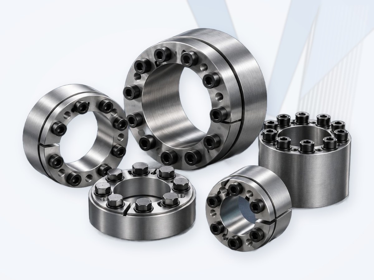
Keyless Locking Assemblies
Internal keyless locking assemblies between shaft and hub for pulleys, gears, sprockets, couplings and drums, plus keyless rigid…
View →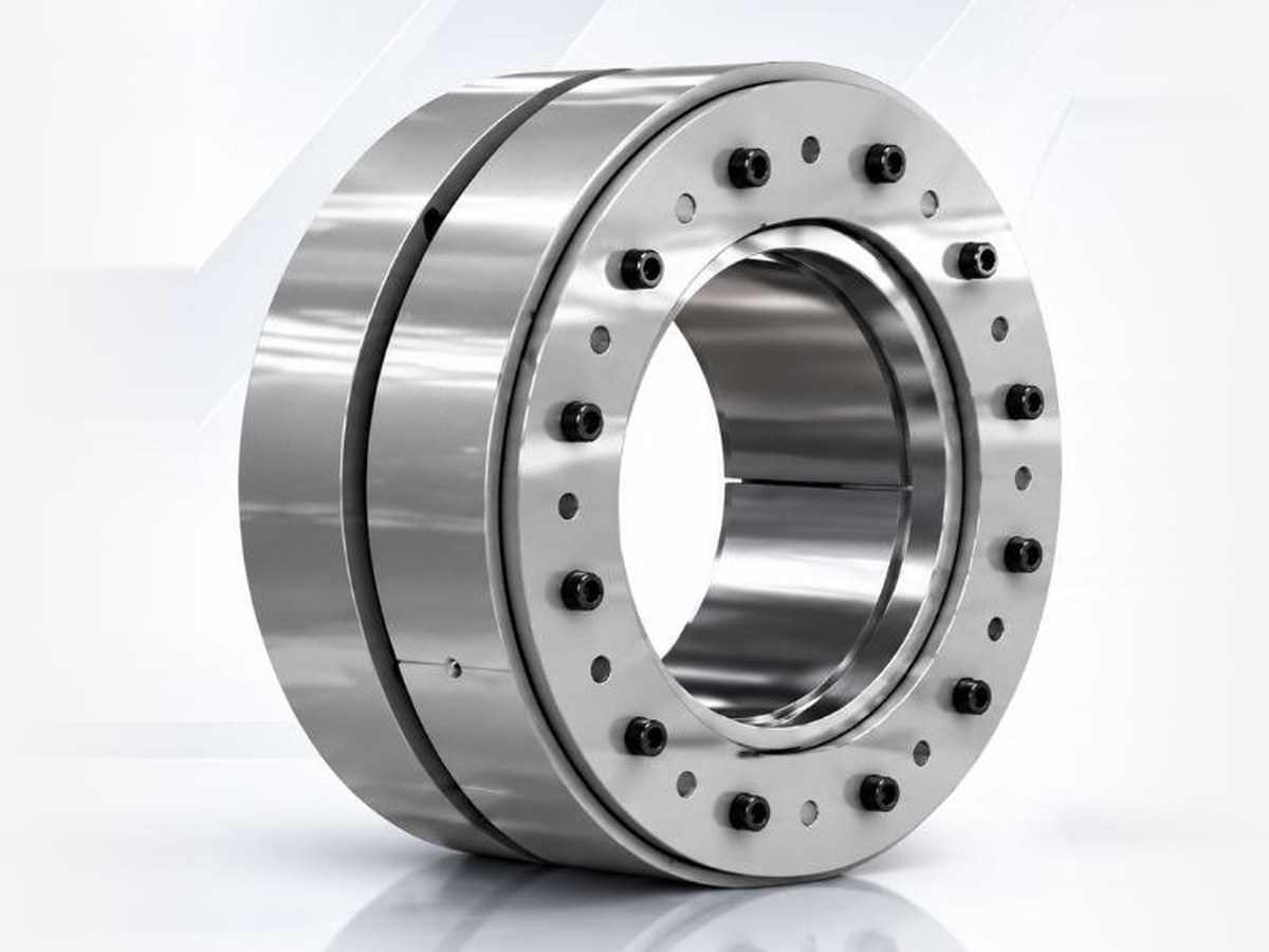
Shrink Discs
External shrink discs clamping a hollow hub onto the shaft - gearbox hollow shafts, conveyor drives and heavy…
View →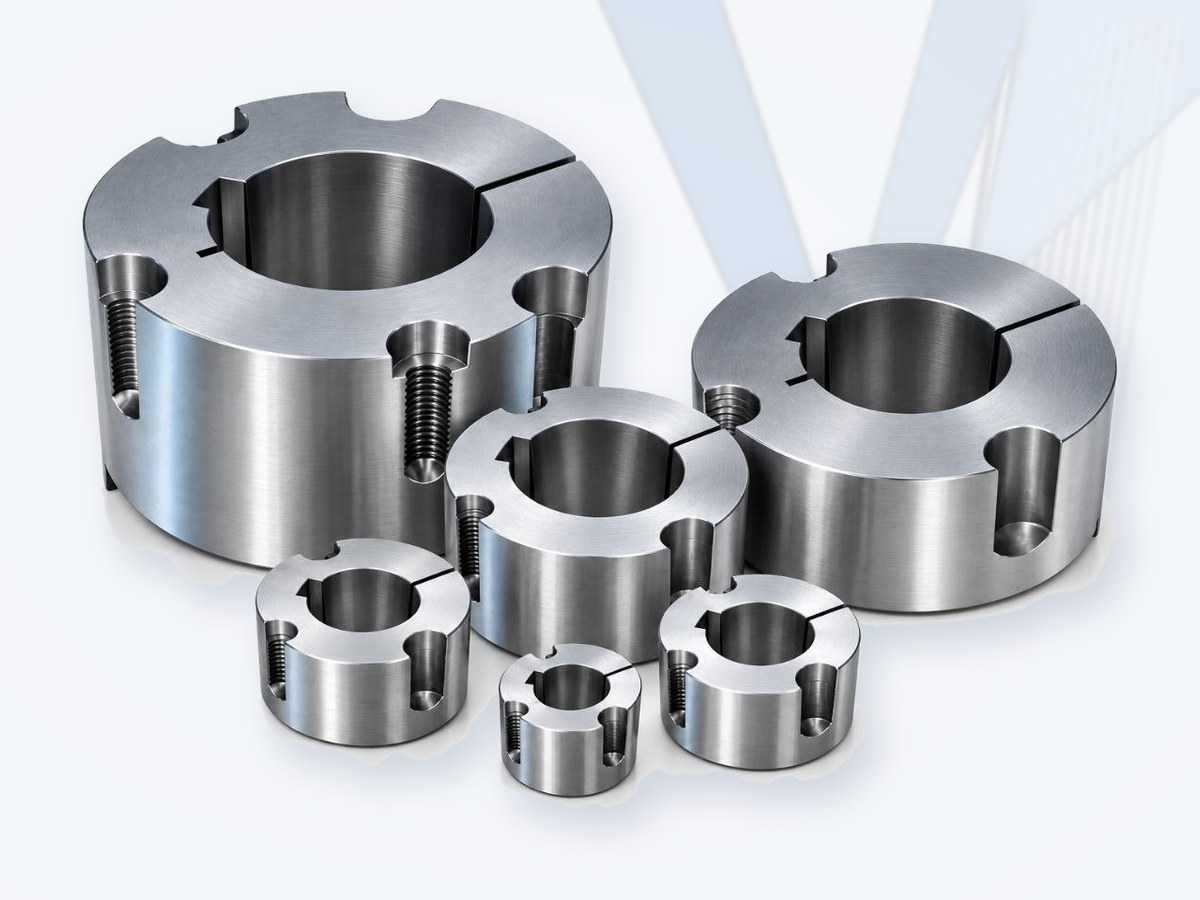
Taper Bushes
Split taper bushes, sizes 1008 to 6050, for pulleys, sprockets and couplings - bores, keyways, slip torque and…
View →Related Shaft Components
Industrial bushings, hubs, adapters and shaft-to-hub connection components - engineering selection, replacement and interchange.
View →What is a locking device?
A locking device is a mechanical connection used to secure a rotating shaft to a hub and transmit torque and, where applicable, axial force without unintended relative movement. Industrial shaft-hub systems include keyless internal locking assemblies, external shrink discs, taper bushings and other engineered friction connections.
In a typical keyless locking assembly, tightening screws create axial force that acts through tapered surfaces to generate controlled radial pressure at the shaft and hub interfaces. Torque and axial force are then transmitted primarily by friction. This differs fundamentally from a conventional keyed joint, where a key and keyway provide the principal positive torque-transmission feature.
Terminology matters: taper-lock/taper bush systems are useful shaft-hub mounting devices, but many conventional versions use a key and should not automatically be described as fully keyless friction-locking assemblies.
Why Use Keyless Shaft-Hub Connections?
- Backlash-free connection: correctly designed friction joints can provide a rigid connection suitable for reversing and cyclic drives.
- No conventional keyway required: true keyless designs avoid the stress concentration associated with a keyway in the shaft/hub.
- Accurate positioning: axial and angular position can often be set before final tightening.
- High torque density: load is distributed over cylindrical contact surfaces rather than concentrated at a key.
- Controlled assembly: repeatable performance is possible when screw torque, lubrication state, surface condition and tolerances match the manufacturer's instructions.
- Serviceability: many designs can be removed and reused, subject to inspection and the manufacturer's reuse criteria.
Do Not Mix Product Classes
A shrink disc, an internal locking assembly and a taper bushing may all connect a shaft and hub, but they do not create the same stress state or interface. Their torque ratings, tolerances, surface requirements, centering behavior and installation procedures are not directly transferable.
Main Types of Industrial Shaft-Hub Locking Systems
| Type | Working principle | Typical applications |
|---|---|---|
| Internal keyless locking assembly | Installed between shaft and hub; tapered rings generate radial pressure at the shaft and hub interfaces. | Pulleys, gears, sprockets, flywheels, couplings, drums. |
| External shrink disc | Mounted around a hollow hub. Clamping action compresses the hollow hub onto an inner shaft. | Gearbox hollow shafts, conveyor drives, heavy machinery, process equipment. |
| Keyless rigid coupling / shaft connector | Friction-based assembly used to rigidly connect shaft ends or create a rigid external connection. | Line shafts, rigid shaft joining, synchronized drive connections. |
| Taper bush / taper-lock style bushing | Split tapered bush is drawn into a matching tapered hub; many standard systems also use a key. | V-belt/timing pulleys, sprockets, couplings, general machinery. |
| Self-locking / keyless taper-style bushing | Special design combining tapered mounting geometry with friction-based locking; exact mechanism is product-specific. | Quick-change or adjustable mounting where the selected manufacturer documents keyless operation. |
Internal vs External Friction Locking
Internal locking assembly: the locking element sits between shaft and hub. Selection must consider shaft contact pressure, hub contact pressure, hub wall thickness and whether the device is self-centering.
External shrink disc: the shrink disc acts outside a hollow hub and generates the clamping pressure needed for the hollow hub-to-shaft friction joint. The hollow hub geometry, wall thickness, material and shaft fit are therefore central to the calculation.
Self-Centering vs Non-Self-Centering
Some locking assemblies center the hub relative to the shaft as they are tightened; others primarily provide clamping and require a separate pilot, fit or centering feature. This distinction is especially important for pulleys, gears, high-speed rotating components and applications with strict runout requirements.
Do not assume that a friction locking device automatically provides precision centering. Verify the exact manufacturer's centering behavior and runout guidance.
Keyless vs Keyed Connection
| Feature | Keyless friction locking | Conventional keyed joint |
|---|---|---|
| Torque path | Distributed friction over cylindrical interfaces. | Concentrated load through key/keyway plus shaft-hub contact. |
| Shaft keyway | Normally not required. | Normally required. |
| Position adjustment | Often continuously adjustable before tightening. | Usually constrained by key/keyway geometry. |
| Capacity basis | Highly dependent on friction coefficient, contact pressure and screw preload. | Dependent on key/keyway stresses, fit and hub/shaft design. |
| Installation sensitivity | Screw torque, sequence, surface condition and lubrication state are critical. | Fit, key dimensions, keyway quality and retention are critical. |
Engineering Selection Procedure
Correct selection requires both load capacity and interface verification. A locking device should never be selected from shaft diameter, catalog appearance or outside dimensions alone.
| Step | Engineering check | Required review |
|---|---|---|
| 1 | Define geometry | Shaft diameter, hub bore, hub OD, hub length, hollow-hub wall thickness, available axial/radial space and assembly access. |
| 2 | Define tolerances & surfaces | Shaft/hub tolerances, surface roughness, coatings/plating and the contact-surface condition required by the manufacturer. |
| 3 | Calculate operating torque | Base relationship: T [Nm] = 9550 x P [kW] / n [rpm]. Apply the appropriate design/service factor and verify peak/start/reversing torque. |
| 4 | Check axial force | If thrust is transmitted, verify allowable axial force and use the manufacturer's combined-load method when torque and axial force act simultaneously. |
| 5 | Check centering/runout | Determine whether the device is self-centering or requires a separate pilot/fit; verify runout for speed-sensitive components. |
| 6 | Check hub stress | Verify permissible hub pressure, minimum hub OD/wall thickness, hub material yield strength and any required stress calculation. |
| 7 | Check shaft stress | Where published, verify shaft contact pressure and shaft material limits, especially for hollow or thin-wall shafts. |
| 8 | Check speed & balance | Verify maximum speed, centrifugal effects, balance/runout and any limitations on rotating screw assemblies. |
| 9 | Check environment | Temperature, corrosion, dust, washdown, hazardous area, coating and material compatibility. |
| 10 | Verify installation | Specified screw tightening torque, tightening sequence, lubricant condition, mounting/removal method and inspection/reuse criteria. |
Torque Calculation - Starting Point Only
T = 9550 x P / n (T in Nm, P in kW, n in rpm). This equation calculates drivetrain torque; it does not by itself determine the allowable capacity of a locking assembly. Final capacity must come from the selected manufacturer's current rating method and must reflect the actual friction conditions, screw preload, geometry, tolerances and combined loading.
Combined Torque and Axial Force
When torque and axial force act simultaneously, the friction capacity is shared between circumferential and axial load components. Manufacturers may express the interaction through a resultant-load equation, reduction factor or rating chart. Do not independently approve both maximum torque and maximum axial force unless the catalog explicitly permits that combination.
Hub Pressure & Material Strength
Radial clamping pressure creates circumferential stress in the hub. For thin hubs, hollow hubs or lower-strength materials, hub stress can become the governing selection limit even when nominal torque capacity appears adequate. Check the manufacturer's minimum hub outside diameter, hub-pressure data and calculation procedure.
Important: published torque capacity is valid only under the manufacturer's stated assumptions for friction coefficient, surface condition, screw tightening and tolerances.
Installation Conditions Are Part of the Rating
Keyless friction joints are highly sensitive to assembly conditions. The selected product's installation instructions are part of the engineering specification, not merely a maintenance note.
- Screw tightening torque: use calibrated tools and the exact value specified for the product.
- Tightening sequence: many assemblies require progressive tightening in multiple passes rather than one-pass final torque.
- Lubrication state: screw threads, screw heads, tapers and shaft/hub contact surfaces may require different conditions. Never add grease, oil or anti-seize unless the instructions allow it.
- Surface finish: excessively smooth, rough, coated or contaminated surfaces can change friction performance.
- Tolerances: shaft and hub fits influence pressure distribution, centering and transmissible load.
- Removal: follow the specified release-screw or staged loosening procedure; stored elastic energy can make improper disassembly hazardous.
| Common error | Why it is risky |
|---|---|
| Selecting only by shaft diameter | Different series with the same bore can have very different torque, pressure and hub requirements. |
| Using catalog maximum torque without duty review | Starts, shock, reversing and peak loads may exceed steady operating torque. |
| Ignoring axial load | Combined torque/thrust can reduce available friction capacity. |
| Assuming self-centering | Can create excessive runout or eccentricity if a separate pilot is actually required. |
| Ignoring hub OD/material | May overstress or permanently deform the hub. |
| Changing lubricant or anti-seize | Can alter screw preload and/or interface friction, invalidating published ratings. |
| Substituting screw grade or quantity | Changes preload and clamping behavior; use only approved hardware. |
| Assuming dimensional interchangeability | Same d/D/L does not guarantee equal torque, pressure, centering or installation requirements. |
Replacement & Interchange Evaluation
An equivalent locking device is an engineered replacement, not a visual or dimensional cross-reference. MECHATRIC first identifies the installed device, then compares interface, performance and installation requirements against current manufacturer data.
| Parameter | Replacement check |
|---|---|
| Original identity | Manufacturer, series, full part number, size, catalog/drawing revision. |
| Geometry | Shaft diameter, hub bore, device OD/width, hub OD/length, available axial/radial space. |
| Capacity | Operating/design/peak torque, axial force and combined-load capability. |
| Pressure/stress | Shaft and hub contact pressure, minimum hub OD/wall thickness and material strength. |
| Centering | Self-centering vs non-self-centering, pilot requirements and allowable runout. |
| Installation | Screw number/size/grade, tightening torque/sequence, lubrication and surface requirements. |
| Operating limits | Speed, temperature, corrosion, duty cycle, starts/reversals and environment. |
| Removal/service | Disassembly method, reuse criteria, replacement screws and maintenance access. |
MECHATRIC Interchange Classification
- Direct Interchange: interface, capacity, installation requirements and operating limits are verified for the specified application.
- Dimensionally Compatible: principal dimensions fit, but capacity, pressure, centering or installation details still require confirmation.
- Functionally Equivalent: performs the required shaft-hub function but may require dimensional, hub or installation changes.
- Engineering Review Required: a candidate has been identified but is not yet approved as a verified replacement.
Typical Applications
- Conveyors: drive pulleys, head/tail pulleys, drums, sprockets and gearbox output connections.
- Mining & cement: crushers, mills, bucket elevators, fans and heavy-duty material handling.
- Steel: rolling/processing equipment, gear drives, fans and auxiliary machinery.
- Oil, gas & petrochemical: rotating-equipment packages, mixers, blowers, fans and auxiliary drives.
- Power generation: fans, cooling systems and rotating auxiliaries.
- General machinery & OEM: gears, flywheels, timing pulleys, V-belt pulleys, couplings and indexing systems.
Engineering Data Required for RFQ
| RFQ group | Information required |
|---|---|
| Original unit | Manufacturer, series, full part number, catalog page, nameplate or drawing. |
| Shaft | Diameter, tolerance, material, solid/hollow construction, surface finish, coating and keyway if present. |
| Hub | Bore, OD, length/wall thickness, material, tolerance, surface finish and centering feature. |
| Performance | Power, speed, operating torque, design/peak torque and axial force. |
| Duty | Starts/hour, reversing, shock, load variation, operating hours and emergency loads. |
| Installation | Available axial/radial space, access, mounting orientation and centering/runout requirement. |
| Environment | Temperature, dust, humidity, corrosion, washdown and hazardous-area requirements. |
| Documents | Photos, dimensional drawing, existing datasheet/catalog and equipment arrangement. |
| Request | Exact replacement, alternative brand, redesign, higher capacity or troubleshooting. |
Leading Manufacturers Worldwide
Well-known European, American and Asian (Japanese and Korean) manufacturers of locking assemblies & shaft-hub connections.
| Manufacturer | Country | Product focus |
|---|---|---|
| RINGFEDER | Germany | Locking assemblies, shrink discs, couplings |
| KTR Systems | Germany | ROTEX, BoWex, RADEX-N couplings; CLAMPEX locking devices; brakes |
| BIKON | Germany | Locking assemblies |
| STUWE | Germany | Shrink discs |
| SIT S.p.A. | Italy | Flexible, disc, gear and zero-backlash couplings; pulleys, belts, SIT-LOCK, taper bushes |
| Tollok (Regal Rexnord) | Italy | Locking assemblies and shrink discs |
| Fenner Drives | United Kingdom | Taper-Lock bushes, pulleys, couplings, keyless bushings |
| Tsubaki | Japan | Couplings, POWER-LOCK, backstops, chains |
Listed for market information only. Brand names belong to their owners; their mention does not imply that MECHATRIC represents, distributes for or is authorized by these manufacturers. Product availability and equivalents are confirmed per enquiry.
MECHATRIC Engineering Support
MECHATRIC supports OEMs, maintenance teams, EPCs and industrial buyers with keyless locking-device selection, shaft-hub connection review, shrink-disc application assessment, replacement/interchange evaluation, troubleshooting and RFQ preparation. Send the existing part number, shaft/hub dimensions, hub material, motor power, RPM, transmitted torque, axial load and available drawings/photos for technical review.
Technical & content governance: locking-device ratings and installation requirements are manufacturer-specific. Final selection must always be verified using the current technical catalog and installation instructions for the chosen product, including torque, axial load, combined loading, shaft/hub pressure, tolerances, surface condition, friction assumptions, screw tightening and operating limits. MECHATRIC does not claim direct interchangeability, a universal friction coefficient, universal tightening torque or universal hub-pressure limit without exact manufacturer and application evidence. Brand/family references do not by themselves imply representation, authorization or commercial partnership.
Frequently Asked Questions
Is every locking device keyless?
No. Internal locking assemblies and shrink-disc joints are commonly keyless friction connections, while many conventional taper-bush systems use a key.
Can I select a locking assembly only by shaft diameter?
No. Torque, axial force, hub geometry/material, contact pressure, centering, speed, tolerances, surface condition and installation method must also be checked.
What is the difference between a locking assembly and a shrink disc?
An internal locking assembly sits between shaft and hub. A shrink disc clamps the outside of a hollow hub so that the hub grips the inner shaft.
Can torque and axial force ratings be used simultaneously?
Not automatically. Use the selected manufacturer's combined-load method.
Are two locking devices with the same dimensions interchangeable?
Not necessarily. Torque capacity, contact pressure, screw preload, centering behavior, tolerances and installation conditions may differ.
Can I lubricate the shaft/hub contact surfaces?
Only if the manufacturer's instructions explicitly permit it. Friction conditions directly affect capacity.
Does a keyless connection eliminate maintenance?
No. Correct installation, bolt/screw condition, corrosion, fretting evidence and joint integrity should be inspected according to the application and manufacturer guidance.