
Gear Couplings
Engineering definition, selection, configurations, replacement & interchange guide.
Industrial Gear Couplings
Engineering support for industrial gear coupling selection, sizing, application review, retrofit, replacement, interchange evaluation and RFQ preparation.
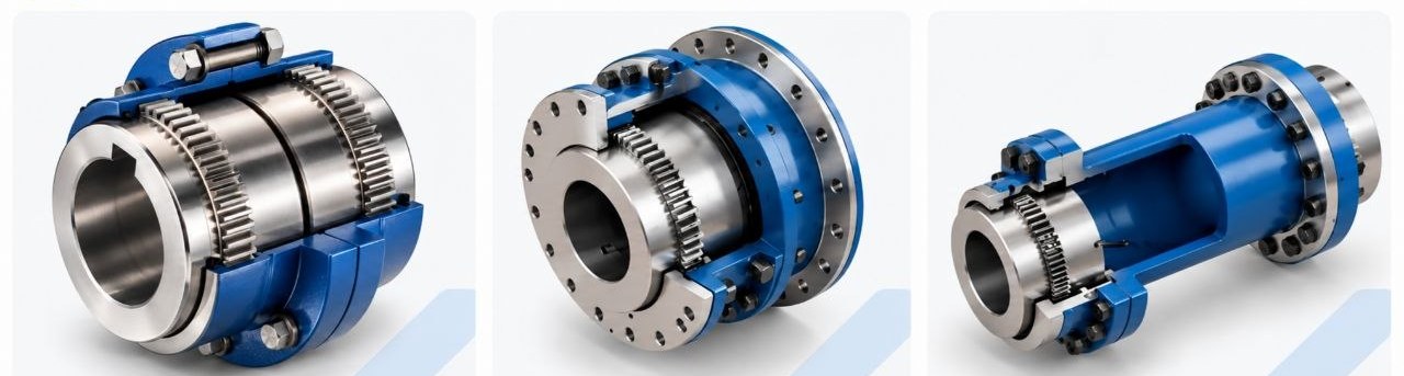
Gear Coupling Families
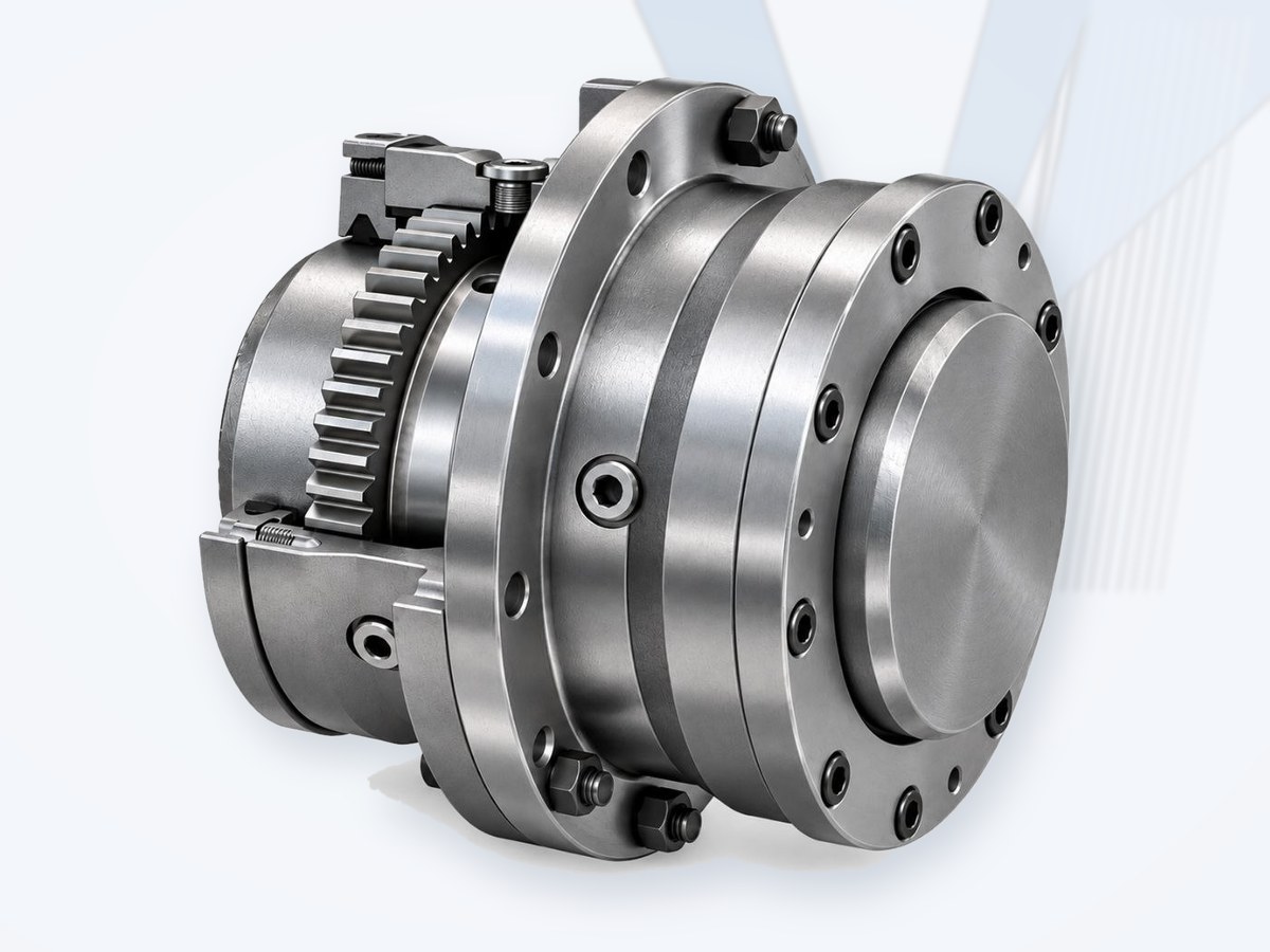
FLENDER ZAPEX
Torsionally rigid gear couplings (ZAPEX / N-ZAPEX) for heavy industrial drives.
View Product →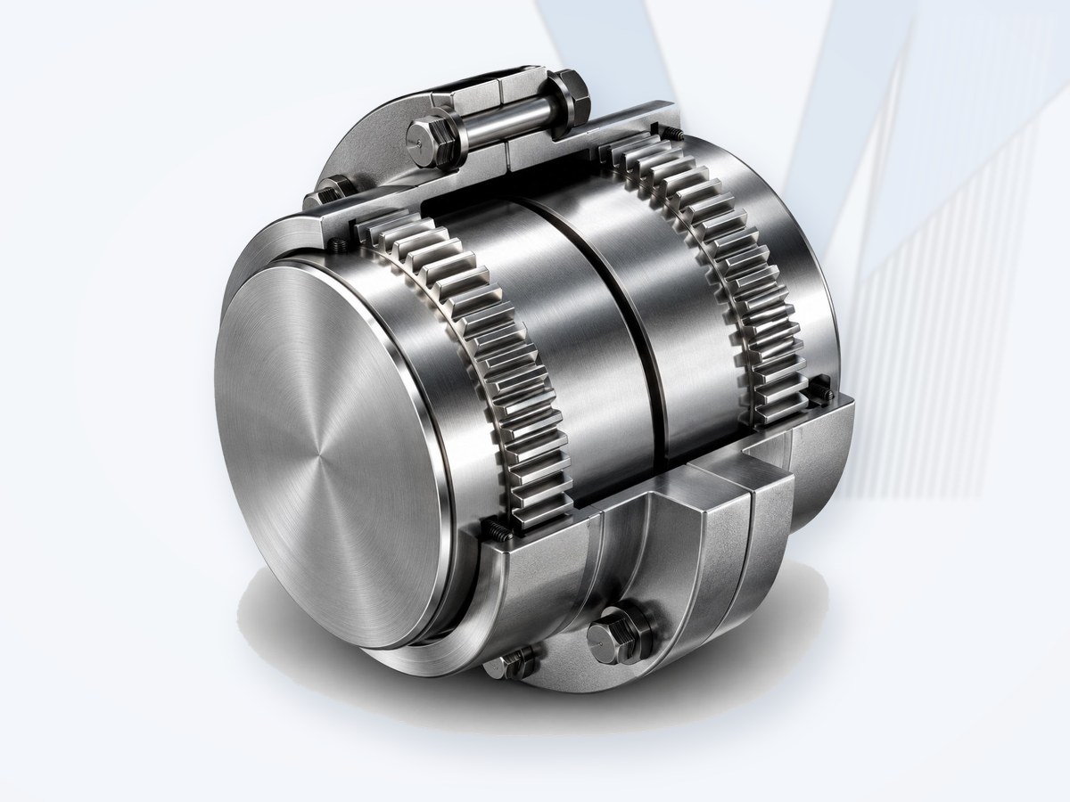
Falk Lifelign
Gear couplings from Regal Rexnord - continuous-sleeve, flanged-sleeve, spacer, floating-shaft and special arrangements.
View Details →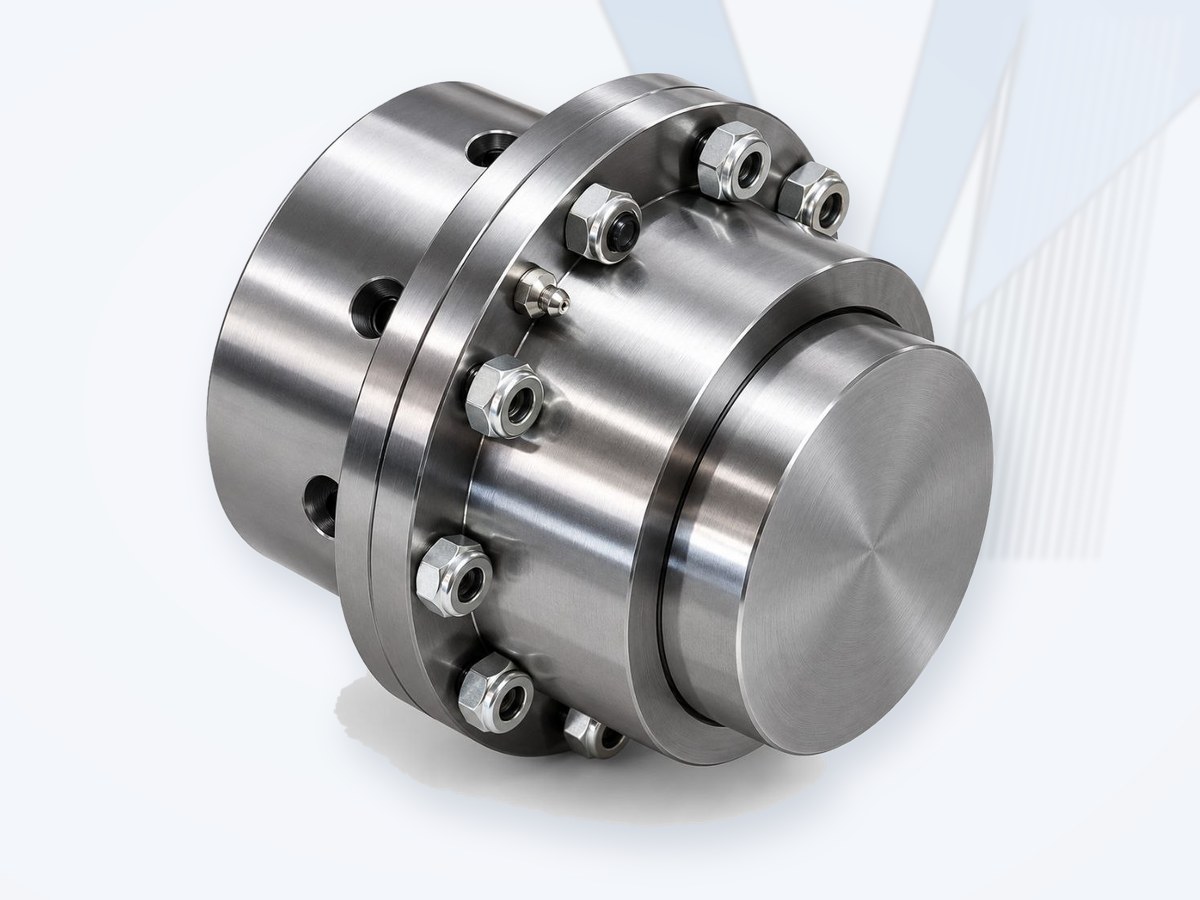
MAINA
Italian gear couplings for heavy-duty industrial and steel-mill drives.
View Details →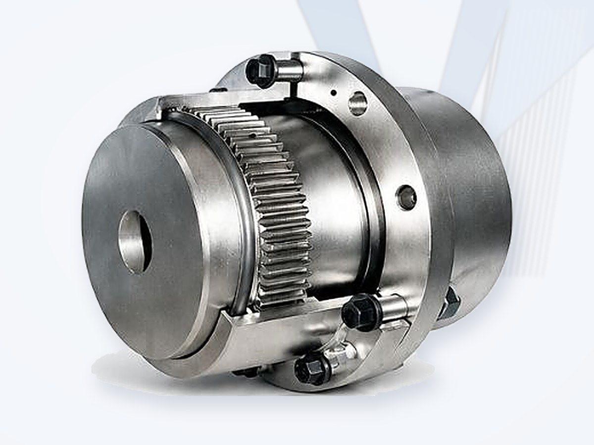
WESTCAR ROTOGEAR
Italian crowned-tooth RE series gear couplings - sizes 40 to 450, nominal torque 1.7 to 835 kNm, standard, spacer, vertical, sliding and disengaging executions.
View Details →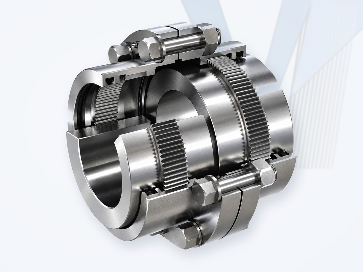
KCP (South Korea)
Gear couplings - type, size and data on request.
View Details →Falk Lifelign
Brand: Falk (Regal Rexnord, USA)
Falk Lifelign gear couplings are a widely installed American series for heavy industrial drives. Main executions: G10 (continuous sleeve) and G20 (flanged sleeve), plus spacer, floating-shaft, slide, shear-pin, brake-wheel / brake-disc and vertical arrangements.
- Double-engagement (two gear meshes) for parallel, angular and axial misalignment; single-engagement for floating-shaft arrangements.
- Crowned external hub teeth in an internally toothed sleeve - torsionally rigid, high torque density.
- Grease or oil lubricated, sealed sleeve.
For a quotation send: existing coupling type and size (nameplate or drawing), shaft diameters and keyways, distance between shaft ends, power, speed, driving / driven machine and service factor.
Information only, based on manufacturer literature; brand names belong to their owners. MECHATRIC does not represent this manufacturer and supplies original or equivalent products after dimensional and rating check.
MAINA
Brand: MAINA (Italy)
MAINA manufactures gear couplings for heavy-duty industrial drives, including steel-mill, crane and conveyor applications, in standard, spacer, floating-shaft and special executions.
- Double-engagement (two gear meshes) for parallel, angular and axial misalignment; single-engagement for floating-shaft arrangements.
- Crowned external hub teeth in an internally toothed sleeve - torsionally rigid, high torque density.
- Grease or oil lubricated, sealed sleeve.
For a quotation send: existing coupling type and size (nameplate or drawing), shaft diameters and keyways, distance between shaft ends, power, speed, driving / driven machine and service factor.
Information only, based on manufacturer literature; brand names belong to their owners. MECHATRIC does not represent this manufacturer and supplies original or equivalent products after dimensional and rating check.
KCP (South Korea)
Brand: KCP (South Korea)
KCP gear couplings for general industrial drives. Detailed type and size data will be added when the full KCP catalogue is available; meanwhile send the existing coupling data for identification.
- Double-engagement (two gear meshes) for parallel, angular and axial misalignment; single-engagement for floating-shaft arrangements.
- Crowned external hub teeth in an internally toothed sleeve - torsionally rigid, high torque density.
- Grease or oil lubricated, sealed sleeve.
For a quotation send: existing coupling type and size (nameplate or drawing), shaft diameters and keyways, distance between shaft ends, power, speed, driving / driven machine and service factor.
Information only, based on manufacturer literature; brand names belong to their owners. MECHATRIC does not represent this manufacturer and supplies original or equivalent products after dimensional and rating check.
What is a gear coupling?
A gear coupling is a flexible mechanical power-transmission coupling that connects two rotating shafts through externally toothed hubs engaging internally toothed sleeves. The geared engagement transmits torque while the tooth geometry and internal clearances allow specified shaft movement and misalignment.
Gear couplings are widely used in high-torque industrial drives including motors, gearboxes, pumps, compressors, conveyors, cranes, hoists, mills, rolling equipment and heavy process machinery.
Unlike an elastomeric coupling, the primary torque path is metallic. Unlike a conventional disc coupling, a gear coupling normally depends on lubricated tooth engagement and therefore requires appropriate lubrication, sealing, alignment and maintenance.
Gear coupling flexibility does not eliminate the need for accurate shaft alignment. Published misalignment capability is an operating limit, not an installation target.
How a Gear Coupling Works
Torque passes from the driving shaft into a geared hub, through the sleeve tooth engagement and into the opposite hub and driven shaft. Crowned or otherwise modified tooth geometry, together with designed clearances, permits controlled angular movement and sliding at the tooth flanks.
Double vs Single Engagement
Double engagement gear couplings have two flexible gear meshes and can accommodate angular misalignment at each mesh; in a properly selected arrangement this also allows parallel/offset misalignment and end movement within manufacturer limits.
Single engagement gear couplings have one flexible gear mesh and one rigid half. They are used where only angular articulation is required at that location, such as floating-shaft and certain three-bearing arrangements.
Typical Benefits
- High torque density - strong metallic tooth engagement can transmit substantial torque in a compact envelope.
- Configuration flexibility - close-coupled, spacer, floating-shaft, vertical, brake, slide, disconnect, insulated and overload-protection arrangements are possible.
- Large bore capability - useful for heavy machinery and low-speed/high-torque shafts, subject to exact size and hub design.
- Serviceable construction - sleeves, seals, fasteners and lubrication can be inspected and maintained according to manufacturer procedures.
Main Gear Coupling Configurations
| Configuration | Engineering purpose |
|---|---|
| Continuous sleeve - double engagement | Compact arrangement with two flexing gear meshes for general close-coupled service. |
| Continuous sleeve - single engagement / floating shaft | One flexible engagement used in floating-shaft or multi-bearing arrangements. |
| Flanged sleeve - double engagement | Common close-coupled heavy-duty design; accommodates combined angular/offset misalignment and end float within design limits. |
| Single engagement | One flex half and one rigid half; primarily accommodates angular movement and is used with floating shafts or three-bearing drive trains. |
| Spacer | Increases shaft separation and can simplify servicing of pumps, compressors and other connected equipment. |
| Floating shaft | Used when the equipment separation is too great for a normal spacer; shaft/span and critical-speed/balance checks are required. |
| Vertical | Modified/centered construction for vertical or inclined shaft arrangements; exact thrust and inclination capability is manufacturer-specific. |
| Brakewheel / disc-brake | Integrates a braking surface for cranes, hoists, conveyors and similar applications. |
| Slide | Designed for applications requiring axial movement, such as thermal expansion or adjustment. |
| Disconnect / inching-drive | Allows equipment or auxiliary/inching drives to be connected or disconnected at standstill, depending on design. |
| Insulated | Provides electrical isolation between shafts for specified applications; not a substitute for high-potential electrical protection. |
| Shear-pin | Provides mechanical disconnection under a defined overload/jam condition; shear setting requires system analysis. |
| Rigid / rigid-thrust | Used where misalignment accommodation is not required; special vertical/thrust arrangements are manufacturer-specific. |
Typical Applications & Industries
| Applications | Industries |
|---|---|
| Motor-to-gearbox and gearbox-to-machine high-torque drives | Steel & Metals; Heavy Industry; OEM |
| Pumps and compressors (incl. spacer arrangements) | Oil & Gas; Petrochemical; Power; Water & Wastewater |
| Conveyors, mills and heavy process machinery | Mining; Cement; Bulk Material Handling |
| Cranes and hoists (incl. brakewheel / disc-brake designs) | Ports; Steel; Material Handling |
| Rolling and forming equipment | Steel & Metals |
Gear Coupling Selection - Standard Engineering Procedure
The standard method is suitable for many motor-, turbine- or engine-driven applications. Selection begins with actual transmitted power or torque and coupling speed, then applies the service factor specified for the driven machine and prime mover.
Define the application
Record driver and driven equipment, actual transmitted power, coupling rpm, duty cycle, shock/vibration, starts/stops, reversing duty, shaft diameters, shaft gap/DBSE, fit/key details, available envelope and any special axial movement, brake or vertical requirement.
Calculate system torque
System Torque (Nm) = kW x 9549 / rpm. Use actual transmitted power where known. Motor or turbine nameplate power may be used as an initial basis when actual duty is unavailable, subject to engineering review.
Apply the correct service factor
Required Minimum Coupling Rating = Service Factor x System Torque. Service factor is application- and manufacturer-specific. It should not be copied blindly between different coupling manufacturers or product families.
Select type and size
Choose the configuration required by the shaft arrangement and maintenance philosophy, then select a coupling whose published rating meets or exceeds the required minimum rating.
Perform the mandatory checks
Bores & fits, speed, dimensions, misalignment, lubrication and environment - see the table below.
| Check | Engineering requirement |
|---|---|
| Bores & fits | Verify both shaft diameters, keyways, interference/clearance fit, hub length and shaft-end geometry. |
| Speed | Operating and maximum speed must be within the exact type/size limit. Balance requirements may become important at elevated speed. |
| Dimensions | Check shaft gap/DBSE, hub length, overall length, outside diameter, bolt/cover clearance and maintenance access. |
| Misalignment | Check angular, parallel/offset and axial/end-float requirements against the selected configuration. |
| Lubrication | Verify lubricant type/grade, fill quantity, seals and relubrication/inspection requirements. |
| Environment | Temperature, moisture, dust, corrosive material, hazardous-area and project specifications. |
Do not stop at torque rating. Bore capacity, speed, dimensions, tooth movement, lubrication and the actual shaft arrangement can govern the final selection.
When the Standard Method Is Not Enough
High peak loads, brake applications, high-frequency axial sliding and shear-pin couplings require a more refined, formula-based review. Rapid direction changes and torque reversals also require special attention.
High Peak & Reversing Loads
Where reliable system peak torque is known, use it directly as an engineering input. Reversing, repetitive or inertia-driven peaks can require a higher selection torque than the normal service-factor method indicates.
Brake Applications
If a brakewheel or disc brake is integral with the coupling and brake torque exceeds normal motor-transmitted torque, the brake duty can govern coupling selection. Use the selected manufacturer's method and verified brake torque.
High-Frequency Axial Sliding
Slide gear couplings are intended for axial movement such as thermal expansion or machine adjustment. Frequent sliding increases tooth movement and wear; manufacturer-specific selection corrections and lubrication requirements must be applied.
Shear-Pin / Jam Protection
Shear-pin arrangements physically disconnect the drive when the calibrated pins fail. The required shear setting must be based on system analysis and the allowable torque of the connected equipment - not on a generic percentage copied from another application.
Torsional & Dynamic Review
For engine drives with significant torque fluctuation, dynamically sensitive trains, operation near a torsional critical speed or severe reversing duty, a mass-elastic/torsional analysis may be necessary.
Misalignment, Tooth Loading & Alignment
Gear couplings accommodate specified movement by relative motion at the geared engagement. Excessive misalignment increases sliding, contact stress, heat generation and lubricant demand. Accurate initial alignment reduces these effects and supports longer tooth and seal life.
MECHATRIC engineering rule: use the manufacturer's recommended installation alignment values where available; never treat the maximum published operating misalignment as the preferred setup condition.
Lubrication & Maintenance
- Use only lubricant type and viscosity/grade approved for the exact gear coupling.
- Verify fill quantity and distribution before operation; improper lubrication can accelerate tooth wear.
- Inspect seals, gaskets, sleeves/flanges, fasteners and evidence of leakage or contamination.
- During overhaul, inspect tooth flanks for wear, pitting, fretting, scoring, abnormal contact and corrosion.
- For slide couplings, vertical arrangements and special speeds, follow the specific manufacturer's lubrication instructions.
Spacer & Floating-Shaft Engineering
Spacer gear couplings are useful where additional distance between shaft ends is needed, especially when maintenance access to pumps, compressors or other machines is important. Floating-shaft assemblies extend this concept for longer spans.
Floating-shaft selection must consider not only coupling torque but also shaft diameter, span, operating speed, mass/inertia and balance/critical-speed behavior. Hub orientation can affect bore capacity, replacement access and permissible offset.
A floating shaft is a drive-train component, not merely a long spacer. Shaft span and dynamic behavior require engineering verification.
Gear Coupling Replacement & Interchange
A replacement should not be selected only because nominal torque, bore or outside diameter appears similar. The existing and proposed couplings must be compared as complete engineered assemblies.
| Step | MECHATRIC review |
|---|---|
| 1. Identify existing coupling | Manufacturer, family, size, type, engagement arrangement, bores/fits, sleeve/flange, seals, fasteners, dimensions, drawing/nameplate/photos. |
| 2. Confirm application | Driver, driven machine, actual kW/torque, rpm, duty, shock, reversing, axial movement, brake duty, environment and failure history. |
| 3. Compare performance | Continuous/peak torque, speed, service-factor basis, misalignment, end float, axial sliding, stiffness/inertia and lubrication. |
| 4. Check interfaces | Bores, keyways, hub lengths, shaft gap/DBSE, overall length, OD, bolt/cover clearance and maintenance access. |
| 5. Review special features | Spacer/floating shaft, vertical support, brakewheel/disc, insulation, shear pin, limited end float, balance or project/API requirements. |
| 6. Classify relationship | Direct Interchange; Dimensionally Compatible; Functionally Equivalent; or Engineering Review Required. |
Interchange Guide - Important Limitation
Published interchange guides comparing flanged-sleeve families from different manufacturers are useful for identifying candidates, but they are not universal proof of direct interchangeability. Current drawings, torque/speed capability, bore limits, fits, bolt geometry, lubrication, materials and the actual application must still be checked.
Do not mix hubs, sleeves, fasteners, seals or other components from different gear-coupling manufacturers unless the combination is explicitly documented or has been fully engineered and approved.
MECHATRIC Interchange Classification
- Direct Interchange - exact engineering verification supports direct replacement for the specified size and application.
- Dimensionally Compatible - physical/interface compatibility is verified, but performance and duty checks remain applicable.
- Functionally Equivalent - satisfies the required function but may differ in dimensions, arrangement or maintenance requirements.
- Engineering Review Required - a possible candidate has been identified but is not approved as a verified interchange.
Gear vs Grid vs Disc vs Elastomeric Couplings
| Type | General characteristic | Typical selection consideration |
|---|---|---|
| Gear | Lubricated metallic toothed engagement; high torque density; flexible through gear-tooth movement. | Heavy industrial/high-torque drives; lubrication, alignment and tooth condition are important. |
| Grid | Lubricated metallic grid; torsionally resilient; good shock cushioning. | General/heavy duty where shock absorption and serviceability are valued. |
| Disc | Metallic disc packs; typically lubrication-free and torsionally rigid. | Precision, speed, low routine maintenance and special-purpose duties depending on design. |
| Elastomeric | Rubber/PU element; damping and compliance; usually lubrication-free. | General machinery where vibration damping and simple element replacement are priorities. |
API & Project-Specification Considerations
Coupling type alone does not establish compliance with API 610, API 671 or another project specification. Any API-related or critical-service gear coupling must be evaluated against the exact project requirements and the selected manufacturer's documented design, materials, balance, inspection, testing and performance data. A gear coupling is not described as "API compliant" unless compliance is documented for the exact product and application.
Reference Gear Coupling Families for Engineering Comparison
Depending on duty, comparison may involve established gear-coupling families such as Falk Lifelign, FLENDER ZAPEX / N-ZAPEX and other qualified industrial gear-coupling designs. These are reference families for engineering comparison and are not automatically interchangeable.
Information Required for Selection / RFQ
| Data group | Information to provide |
|---|---|
| Coupling design | Gear coupling; horizontal/vertical; close-coupled, spacer, floating-shaft or special arrangement. |
| Prime mover | Electric motor, engine or turbine; rated kW; base speed and maximum speed. |
| Driven equipment | Pump, compressor, conveyor, crusher, mill, crane, hoist, fan, gearbox, mixer, etc. |
| Duty | Continuous/intermittent; unidirectional/reversing; smooth/light/heavy shock; vibration level; starts/stops. |
| Torque & speed | Actual transmitted kW/torque; normal rpm; peak/reversing/brake torque where applicable. |
| Shaft interface | Driver/driven shaft diameters, keys/keyways, clearance/interference fit and shaft extension lengths. |
| Installation | Shaft gap/DBSE; envelope; mounting orientation; spacer/floating shaft; axial travel/end float. |
| Environment | Temperature, moisture, dust, corrosive material and hazardous-area requirements. |
| Special engineering | Balance class, mass/WR2/inertia, torsional stiffness, angular/offset/axial movement and applicable specifications. |
| Existing coupling | Make, family, size/type, bores, dimensions, lubricant, drawings, nameplate and photographs. |
Leading Manufacturers Worldwide
Well-known European, American and Asian (Japanese and Korean) manufacturers of gear couplings.
| Manufacturer | Country | Product focus |
|---|---|---|
| FLENDER | Germany | N-EUPEX, RUPEX, ELPEX, ARPEX, ZAPEX, FLUDEX couplings; industrial gear units |
| KTR Systems | Germany | ROTEX, BoWex, RADEX-N couplings; CLAMPEX locking devices; brakes |
| SIT S.p.A. | Italy | Flexible, disc, gear and zero-backlash couplings; pulleys, belts, SIT-LOCK, taper bushes |
| MAINA | Italy | Gear couplings |
| Westcar | Italy | Fluid and gear couplings, drum and disc brakes |
| Renold | United Kingdom | Couplings, freewheels / backstops, chains |
| Regal Rexnord (Falk, Kop-Flex, Thomas, Rexnord) | USA | Grid, gear and disc couplings; gear drives; backstops; roller chain |
| Ameridrives (Regal Rexnord) | USA | Gear and disc couplings |
| Tsubaki | Japan | Couplings, POWER-LOCK, backstops, chains |
| KCP (Korea Coupling) | South Korea | Grid and gear couplings |
Listed for market information only. Brand names belong to their owners; their mention does not imply that MECHATRIC represents, distributes for or is authorized by these manufacturers. Product availability and equivalents are confirmed per enquiry.
Need help selecting or replacing a gear coupling?
MECHATRIC can support new gear-coupling selection, application review, technical cross-reference, replacement/interchange evaluation, spacer and floating-shaft review, RFQ preparation and engineering assessment of alternative solutions.
Engineering reference: Falk Lifelign Gear Couplings (Metric), catalog 451-110M. Manufacturer-specific ratings, service factors, dimensions, speeds, misalignment limits, lubrication requirements and interchange data must be verified against the current documentation for the exact selected product. Exact ratings, dimensions, standards, certifications and interchangeability must be verified for the selected manufacturer, size and application. Brand/family names are used for technical identification and comparison and do not by themselves imply representation, authorization or commercial partnership.
Frequently Asked Questions
What is a gear coupling?
A flexible shaft coupling that transmits torque through externally toothed hubs engaging internally toothed sleeves.
What is the difference between double and single engagement?
Double engagement has two flexible gear meshes and can accommodate combined shaft offset and angular movement within design limits. Single engagement has one flexible mesh and is used where articulation is required at only one coupling plane.
Do gear couplings require lubrication?
Conventional flexible gear couplings do. Lubricant type, fill quantity, sealing and maintenance interval must follow the exact manufacturer's instructions.
When is a spacer or floating-shaft gear coupling used?
A spacer increases distance between shaft ends and can improve maintenance access. A floating shaft is used for longer spans and requires additional shaft/dynamic verification.
Can one brand replace another directly?
Not automatically. Torque, speed, bores, fits, dimensions, tooth geometry, misalignment, lubrication, special features and the actual duty must be reviewed.
When is standard service-factor selection insufficient?
High peak/reversing loads, brake duty, frequent axial sliding, shear-pin applications and dynamically sensitive trains can require a special selection method or torsional review.