
Grid Couplings
Engineering definition, selection, service factor, replacement & interchange guide.
Industrial Grid Couplings
Engineering support for industrial grid coupling selection, sizing, application review, replacement, interchange evaluation and RFQ preparation.
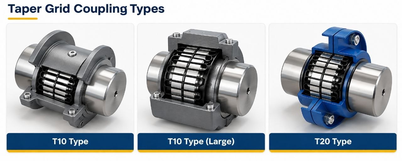
Grid Coupling Families
Falk Steelflex
Tapered grid couplings from Regal Rexnord - T10 horizontal split cover, T20 vertical split cover, spacer and special types.
View Details →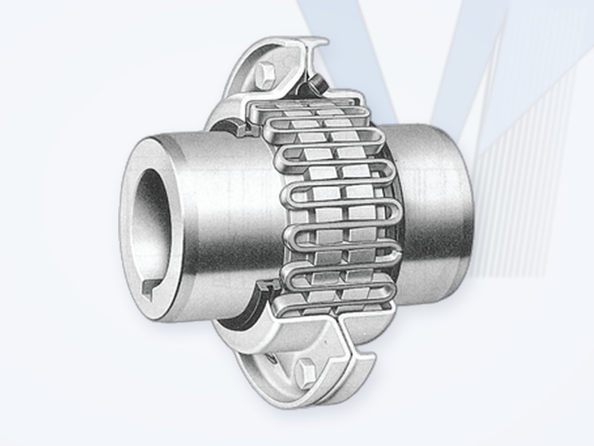
KCP (South Korea)
Taper grid couplings, sizes 1020-1200, H (horizontal split aluminium) and V (vertical split steel) covers; spacer and brake-wheel types; interchangeable with Falk T10 / T20.
View Details →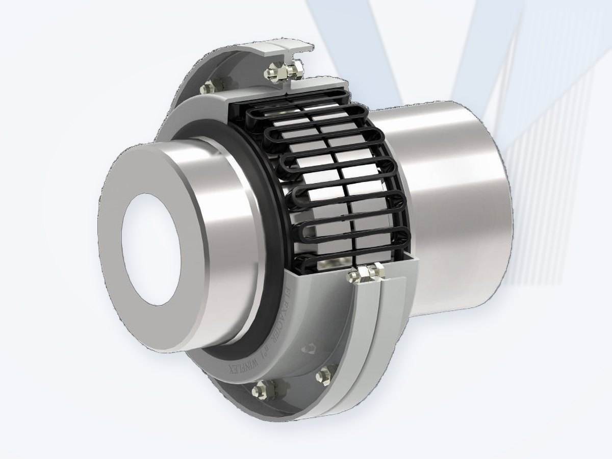
CMD Winflex (France)
All-steel spring-grid couplings, 13 sizes from 90 to 160,000 Nm nominal torque; type T, TL and many special executions.
View Details →Falk Steelflex
Brand: Falk (Regal Rexnord, USA)
Falk Steelflex is the reference design for tapered-grid couplings. A serpentine spring-steel grid runs in the tapered teeth of two hubs; under load the grid contact moves along the taper, giving progressive torsional flexibility, shock and vibration damping and tolerance for parallel, angular and axial misalignment. The grid is lubricated and enclosed in a cover.
- T10: horizontal split cover - grid replaceable without moving the connected machines.
- T20: vertical split cover for higher speeds.
- Spacer, half-spacer, brake-wheel / brake-disc, floating-shaft and taper-bush hub executions.
- Common size range 1020 to 1200 (T10 / T20); KCP T10 / T20 couplings are interchangeable with Falk T10 / T20.
For a quotation send: existing coupling type and size (nameplate or drawing), shaft diameters and keyways, distance between shaft ends, power, speed, driving / driven machine and service factor.
Information only, based on manufacturer literature; brand names belong to their owners. MECHATRIC does not represent this manufacturer and supplies original or equivalent products after dimensional and rating check.
KCP (South Korea)
Brand: KCP (South Korea)
KCP taper grid steel flexible couplings are offered in sizes 1020 to 1200 with H covers (horizontal split, aluminium) or V covers (vertical split, steel), plus KSAS full-spacer, KSFS half-spacer and KSBW brake-wheel types. The grid moves in lubricated grooves to accommodate parallel and angular misalignment and end float, while progressive grid-to-tooth contact provides torsional flexibility and shock damping. KCP states that its grid couplings are interchangeable with the major international brands; under extreme overload the grid shears to protect shafts and connected machinery.
Selection (KCP method): design torque from power, lowest operating speed and the recommended service factor (double the service factor for repeated reversing or frequent irregular load changes); then check the maximum bore and speed of the selected size.
| Size | Install: parallel offset (mm) | Install: angular X-Y (mm) | Operating: parallel offset (mm) | Operating: angular X-Y (mm) | Normal gap (mm) |
|---|---|---|---|---|---|
| 1020 | 0.15 | 0.08 | 0.30 | 0.25 | 3 |
| 1030 | 0.15 | 0.08 | 0.30 | 0.30 | 3 |
| 1040 | 0.15 | 0.08 | 0.30 | 0.33 | 3 |
| 1050 | 0.20 | 0.10 | 0.40 | 0.41 | 3 |
| 1060 | 0.20 | 0.13 | 0.40 | 0.46 | 3 |
| 1070 | 0.20 | 0.13 | 0.40 | 0.51 | 3 |
| 1080 | 0.20 | 0.15 | 0.40 | 0.61 | 3 |
| 1090 | 0.20 | 0.18 | 0.40 | 0.71 | 3 |
| 1100 | 0.25 | 0.20 | 0.50 | 0.84 | 5 |
| 1110 | 0.25 | 0.23 | 0.50 | 0.91 | 5 |
| 1120 | 0.28 | 0.25 | 0.56 | 1.02 | 6 |
| 1130 | 0.28 | 0.30 | 0.56 | 1.19 | 6 |
| 1140 | 0.28 | 0.33 | 0.56 | 1.35 | 6 |
| 1150 | 0.30 | 0.41 | 0.60 | 1.57 | 6 |
| 1160 | 0.30 | 0.46 | 0.60 | 1.78 | 6 |
| 1170 | 0.30 | 0.51 | 0.60 | 2.01 | 6 |
| 1180 | 0.38 | 0.56 | 0.76 | 2.26 | 6 |
| 1190 | 0.38 | 0.61 | 0.76 | 2.46 | 6 |
| 1200 | 0.38 | 0.69 | 0.76 | 2.72 | 6 |
Misalignment capacity per KCP (installation values based on 1/16 degree, operating values on 1/4 degree); coupling life is reduced if limits are exceeded. Source: KCP Grid Coupling catalogue section (Finer Power Transmissions, 2018); verify current torque ratings, bores and speeds for the selected size.
For a quotation send: existing coupling type and size (nameplate or drawing), shaft diameters and keyways, distance between shaft ends, power, speed, driving / driven machine and service factor.
Information only, based on manufacturer literature; brand names belong to their owners. MECHATRIC does not represent this manufacturer and supplies original or equivalent products after dimensional and rating check.
CMD Winflex (France)
Brand: CMD (France)
The CMD Winflex (Flexacier) coupling is an all-steel spring-grid coupling for severe conditions (-20 to +110 C). According to CMD, the special groove profile keeps the spring-to-hub pressure constant while the contact area grows with load, giving progressive torsional stiffness; the large number of teeth and the spring elasticity absorb over-torque and shocks, and the floating mounting of cover and grid avoids significant bearing reactions.
| Size | Nominal torque (Nm) | Max. bore, keyed (mm) | Max. speed without balancing (rpm) |
|---|---|---|---|
| Z | 90 | 28 | 4500 |
| 000 | 190 | 38 | 4500 |
| 00 | 380 | 55 | 3650 |
| 0 | 950 | 55 | 3450 |
| 1 | 1,900 | 80 | 2640 |
| 2 | 3,800 | 110 | 1880 |
| 5 | 8,500 | 105 | 1880 |
| 9 | 12,500 | 130 | 1570 |
| 16 | 24,000 | 180 | 1200 |
| 28 | 48,000 | 230 | 920 |
| 43 | 70,000 | 230 | 750 |
| 70 | 120,000 | 230 | 750 |
| 95 | 160,000 | 270 | 650 |
Executions listed by CMD include type T / TL (standard and long hubs), spacer, extended shaft, high-torque, integrated two-part cover, automatically disengageable, pulley / flywheel adaptation, brake pulley and brake disc versions (types CB, JDA/JDAT, CPF, TDF, TADB, S, BSA/BSAT). Higher speeds are possible with dynamic balancing. Source: CMD Winflex catalogue (01/2020); verify current data for the selected size.
For a quotation send: existing coupling type and size (nameplate or drawing), shaft diameters and keyways, distance between shaft ends, power, speed, driving / driven machine and service factor.
Information only, based on manufacturer literature; brand names belong to their owners. MECHATRIC does not represent this manufacturer and supplies original or equivalent products after dimensional and rating check.
What is a grid coupling?
A grid coupling is a lubricated flexible mechanical shaft coupling that transmits torque through a resilient metallic grid seated in specially formed grooves in two hubs. The spring-like grid flexes as load changes, allowing the coupling to combine relatively high torque capacity with torsional resilience, limited misalignment capability and shock-load cushioning.
Grid couplings are commonly used between electric motors, gearboxes and driven machines such as pumps, fans, blowers, conveyors, crushers, mixers, mills and other industrial rotating equipment.
A useful engineering characteristic of the grid concept is that the grid-to-groove contact changes progressively as torque increases. This can help cushion transient loads while maintaining positive mechanical torque transmission.
A grid coupling is not a substitute for correct shaft alignment. Published misalignment capacity is an operating limit, not an installation target.
How a Grid Coupling Works
Torque flows from the driving shaft into the first hub, through the metallic grid, into the second hub and then to the driven shaft. The grid flexes within the hub grooves under load. The cover retains the lubricant and protects the flexible element and groove contact surfaces.
Correct selection, alignment, lubrication, cover sealing and installation are essential. Coupling life is affected by transmitted load, operating speed, alignment quality, lubrication condition, starts/stops, shock loading and the surrounding environment.
Typical Benefits
- High torque capability for many general and heavy-duty industrial drives.
- Torsional resilience - the metallic grid flexes under load and helps reduce transmitted shock.
- Serviceability - many split-cover designs allow inspection and grid replacement without major movement of connected machines.
- Application range - close-coupled, spacer, floating-shaft, high-speed, brake and special arrangements.
- Mechanical robustness - metallic torque-transmitting element with lubricated hub-groove contact.
Main Grid Coupling Configurations
| Configuration | Typical engineering use |
|---|---|
| Horizontal split-cover, close-coupled | General industrial service. Split cover can simplify inspection and grid replacement without moving connected equipment, depending on design. |
| Vertical split-cover, close-coupled | Useful where cover arrangement, access or higher running-speed capability favors a vertical split design. |
| Full spacer | Removable center section / increased shaft separation; can facilitate maintenance of connected equipment such as pumps. |
| Half spacer | Economical spacer arrangement for applications requiring additional separation and maintenance access. |
| Floating-shaft / piloted | For larger distance between shafts or line-shaft arrangements where a conventional spacer is insufficient. |
| High-speed | Special balanced construction for speeds beyond standard close-coupled design limits; manufacturer verification is essential. |
| Flywheel | Connects an engine flywheel to driven machinery in suitable applications. |
| Brake / controlled-torque / special | Application-specific designs integrating braking surfaces or controlled slipping / overload protection functions. |
Typical Applications & Industries
| Applications | Industries |
|---|---|
| Pumps, fans, blowers, compressors | Oil & Gas; Petrochemical; Power; Water & Wastewater |
| Belt, chain and screw conveyors; feeders | Mining; Cement; Steel; Material Handling |
| Crushers, mills, mixers, agitators | Mining; Cement; Process Industries |
| Bucket elevators and line shafts | Cement; Grain; Bulk Material Handling |
| Rolling / forming and auxiliary drives | Steel & Metals; Heavy Industry |
| General motor-to-gearbox and gearbox-to-machine drives | Industrial Machinery; OEM; EPC |
Grid Coupling Selection - Engineering Procedure
For most motor-, turbine- or engine-driven industrial applications, selection starts with transmitted torque or power and speed, then applies the appropriate manufacturer service factor. The selected coupling must subsequently pass all mechanical and dimensional checks.
Define the application
Identify the driver, driven machine, operating duty, continuous/intermittent operation, starts and stops, load direction, reversing duty, shock level, vibration, environmental conditions and any braking or peak-load condition.
Calculate system torque
System Torque (Nm) = kW x 9549 / rpm. Use the actual transmitted power where known. If only the motor or turbine nameplate rating is available, it may be used as an initial basis subject to engineering review.
Determine the service factor
Use the service factor specified by the manufacturer for the actual driven equipment and prime mover. Service factor is application-dependent; it should not be copied from an unrelated coupling family or manufacturer.
Determine the required minimum coupling rating
Minimum Coupling Rating = Service Factor x System Torque.
Select coupling type and size
Choose the required configuration - close-coupled, spacer, floating-shaft, high-speed or special - then select a size whose published torque rating equals or exceeds the required minimum rating.
Perform the mandatory checks
Speed, bore/shaft interface, shaft gap/DBSE, envelope, misalignment, environment and lubrication - see the table below.
| Check | Engineering requirement |
|---|---|
| Speed | Required rpm must be within the allowable speed for the exact coupling type and size. |
| Bore / shaft interface | Both shaft diameters, keyways, fits and hub details must be feasible. |
| Shaft gap / DBSE | Verify the actual distance between shaft ends and required spacer geometry. |
| Envelope | Check outside diameter, hub length, cover clearance and maintenance access. |
| Misalignment | Verify installation target and operating limits for angular, parallel and axial movement. |
| Environment | Temperature, moisture, dust, corrosive materials and hazardous-area/project requirements. |
| Lubrication | Correct lubricant type, fill quantity, sealing and maintenance requirements. |
High peak torque, repetitive shock, rapid torque reversal and brake applications require additional engineering review. A simple power x service-factor calculation may not be sufficient.
Service Factor - Use It Correctly
Service factor accounts for the severity of the driven machine and operating duty. Published values vary by application and manufacturer. A centrifugal blower, cooling-tower fan, bucket conveyor, reciprocating feeder or hammer mill can require materially different factors.
For MECHATRIC selection work, the service factor is treated as a manufacturer- and application-specific engineering input, not as a universal number.
High Peak Load, Reversing & Brake Duty
Where actual peak torque is known, the selection should be checked against that peak rather than relying only on average transmitted power. Repetitive high peaks, jams, temporary overloads, rapid direction changes and braking can govern coupling size.
For brake applications, the brake torque can become the governing selection torque when it exceeds the normal motor-transmitted torque. Exact formulas and allowable conditions are taken from the selected manufacturer's current engineering documentation.
Misalignment & Alignment
Grid couplings can accommodate specified angular and parallel misalignment, and some designs also permit limited axial movement. However, maximum operating misalignment is not a recommended installation condition. Accurate initial alignment generally improves coupling life and reduces stress on connected shafts, bearings and seals. The permissible values depend on coupling size, configuration, speed, load and lubrication.
MECHATRIC engineering rule: use the manufacturer's recommended installation alignment values whenever available. Do not intentionally install a coupling near its maximum published operating misalignment.
Lubrication & Maintenance
Conventional grid couplings are lubricated couplings. The lubricant reduces friction and wear between the metallic grid and hub grooves while the cover and seals retain lubricant and exclude contamination.
- Use only lubricant grades approved for the exact coupling design.
- Apply the specified lubricant quantity - under-filling and improper filling can reduce reliability.
- Inspect seals, cover condition and evidence of leakage or contamination.
- During overhaul, inspect the grid and hub grooves for wear, fretting, deformation or abnormal contact.
- Follow the selected manufacturer's current relubrication / maintenance instructions.
Extended lubrication intervals claimed for specific products with proprietary lubricants apply only to that verified product and are not generalized to all grid couplings.
Grid Coupling Replacement & Interchange
A replacement grid coupling should not be selected only because the bore, outside diameter or nominal torque looks similar. True equivalency requires a structured comparison of the existing coupling, proposed alternative and actual machine duty.
| Step | MECHATRIC engineering review |
|---|---|
| 1. Identify existing coupling | Manufacturer, series, size, configuration, bores, keyways/fits, grid, cover, seals, dimensions, drawings and photos. |
| 2. Confirm actual application | Driver, driven equipment, power, speed, duty cycle, starts, reversing, shock, vibration, peak torque, environment and failure history. |
| 3. Compare performance | Torque rating, allowable speed, service factor basis, misalignment, torsional behavior, lubrication and operating limits. |
| 4. Check dimensions | Bores, keyways, hub length, shaft gap / DBSE, overall length, outside diameter, cover clearance and maintenance access. |
| 5. Verify special requirements | Balance, inertia / WR2, stiffness, project specifications, hazardous-area requirements and applicable standards. |
| 6. Classify the relationship | Direct Interchange; Dimensionally Compatible; Functionally Equivalent; or Engineering Review Required. |
Component Compatibility Warning
Do not assume that grids, hubs, covers, seals or other grid-coupling components from different manufacturers are interchangeable. Similar appearance or nominal size does not prove compatibility. Differences in grid geometry, groove profile, material, heat treatment, dimensions, fit, lubrication and cover design can affect load distribution and safety.
Component-level interchange is accepted only when supported by manufacturer documentation or a documented MECHATRIC engineering verification.
MECHATRIC Interchange Classification
- Direct Interchange - exact engineering verification supports direct replacement.
- Dimensionally Compatible - physical/interface compatibility verified, with other engineering checks still considered.
- Functionally Equivalent - performs the required function but may differ dimensionally or in configuration.
- Engineering Review Required - a candidate relationship has been identified but is not approved as a verified interchange.
Grid vs Gear vs Disc vs Elastomeric Couplings
| Coupling type | General engineering characteristic | Typical selection consideration |
|---|---|---|
| Grid | Lubricated metallic flexible element; torsionally resilient; good shock-load capability. | General/heavy industrial drives where serviceability and shock cushioning are valued. |
| Gear | Lubricated toothed engagement; high torque density; accommodates specified misalignment. | High torque and compact envelope; lubrication and tooth condition are important. |
| Disc | Metallic disc packs; typically lubrication-free; generally torsionally rigid. | Precision, speed, low maintenance and special-purpose applications depending on design. |
| Elastomeric | Rubber/PU element; damping and compliance; often lubrication-free. | General machinery where vibration damping, simplicity and element replacement are priorities. |
API & Project-Specification Considerations
Coupling type alone does not establish compliance with API 610, API 671 or any other project standard. A grid coupling proposed for an API-related or critical-service application must be evaluated against the exact project specification and the selected manufacturer's documented design, materials, balance, inspection, testing and performance requirements. A grid coupling is not described as "API compliant" unless compliance is documented for the exact product and application.
Information Required for Selection / RFQ
| Data group | Information to provide |
|---|---|
| Driver | Electric motor / engine / turbine; rated power; base and maximum speed. |
| Driven machine | Pump, fan, conveyor, crusher, mill, blower, mixer, gearbox, etc. |
| Duty | Continuous/intermittent; unidirectional/reversing; starts/stops; shock and vibration level. |
| Torque / speed | kW or torque; normal rpm; starting/peak/brake torque if available. |
| Shaft interface | Driver and driven shaft diameters; key/keyway; clearance/interference fit. |
| Installation | Shaft gap / DBSE; available envelope; horizontal/vertical mounting; spacer requirement. |
| Environment | Temperature, moisture, dust, corrosive materials and hazardous-area requirements. |
| Existing coupling | Make, series, size, bores, grid/cover details, lubricant, photos, drawing/nameplate. |
| Engineering data | Required misalignment, balance class, WR2/inertia, stiffness and applicable specifications when relevant. |
Equivalent Designs - Cross-Reference
Use this table to find the equivalent design from another manufacturer. Send the existing part number - MECHATRIC confirms the exact size and rating.
| Coupling type | Falk (Rexnord) | KCP | Relationship |
|---|---|---|---|
| Tapered grid coupling, horizontal split cover | Steelflex T10 | T10 | Same design - interchangeable |
| Tapered grid coupling, vertical split cover | Steelflex T20 | T20 | Same design - interchangeable |
These designs are built to the same concept and interchangeable sizes by several manufacturers. Mechanical ratings (torque, speed, misalignment, element hardness or grid material) can differ slightly between makers and are always checked against the duty before a replacement is confirmed.
Leading Manufacturers Worldwide
Well-known European, American and Asian (Japanese and Korean) manufacturers of grid couplings.
| Manufacturer | Country | Product focus |
|---|---|---|
| CMD | France | Winflex grid couplings |
| Regal Rexnord (Falk, Kop-Flex, Thomas, Rexnord) | USA | Grid, gear and disc couplings; gear drives; backstops; roller chain |
| TB Wood's (Regal Rexnord) | USA | Couplings, sheaves, bushings |
| Dodge (RBC) | USA | Gear reducers, bushings, couplings |
| Tsubaki | Japan | Couplings, POWER-LOCK, backstops, chains |
| KCP (Korea Coupling) | South Korea | Grid and gear couplings |
Listed for market information only. Brand names belong to their owners; their mention does not imply that MECHATRIC represents, distributes for or is authorized by these manufacturers. Product availability and equivalents are confirmed per enquiry.
Need help selecting or replacing a grid coupling?
MECHATRIC supports new grid-coupling selection, application review, technical cross-reference, replacement/interchange evaluation, review of existing coupling data, RFQ preparation and engineering assessment of alternative solutions.
Engineering reference: Falk Steelflex Grid Couplings Application Guide (catalog 421-110M). Exact torque ratings, service factors, speed limits, dimensions, misalignment limits, lubrication requirements, certifications and interchangeability must be verified against current manufacturer documentation and the specific application. Brand names and reference families are used for technical identification/comparison and do not by themselves imply representation, authorization or commercial partnership.
Frequently Asked Questions
What is a grid coupling?
A lubricated flexible shaft coupling that transmits torque through a resilient metallic grid seated in grooved hubs.
What is a taper grid coupling?
A common grid-coupling design using a tapered or spring-like grid with shaped hub grooves to transmit torque and flex under load.
How is a grid coupling selected?
Normally from transmitted power/speed or torque, the manufacturer's service factor and coupling rating, followed by checks of peak load, speed, bores, shaft gap, dimensions, misalignment, lubrication and environment.
Can a grid coupling absorb shock loads?
Grid flexibility and progressive groove contact can cushion transient loads. Exact performance depends on the selected design and application.
Do grid couplings require lubrication?
Conventional grid couplings do. Use the exact grease, fill quantity and maintenance interval specified by the manufacturer.
Can the maximum misalignment be used as the installation target?
No. Accurate initial alignment is preferred. Published maximum operating misalignment is a limit, not a recommended installation condition.
Can one brand replace another directly?
Not automatically. Torque, speed, bores, dimensions, grid/groove design, misalignment, lubrication, duty and component compatibility must be reviewed.
Can grids or covers from different manufacturers be mixed?
Do not assume compatibility. Component-level interchange requires documented manufacturer support or engineering verification.
Are grid couplings API 671 couplings?
Coupling category alone does not establish compliance. Any API or project-standard claim requires verification for the exact design and application.