
SIT LINE-LASER Pulley Alignment Tool
Laser device for quick pulley alignment; corrects axial and angular misalignment; centre distance up to 2 m; max. error 1 mm per metre.
SIT LINE-LASER Pulley Alignment Tool
The SIT LINE-LASER® is a laser alignment tool for belt drives. Correct pulley alignment is a precondition for the rated performance and service life of any belt drive: the LINE-LASER projects a laser line from one pulley onto three control targets placed on the other pulley, so lateral (axial) and angular misalignment become visible at once and can be corrected quickly. Light, reliable and easy to use, it combines the precision of laser technology with simple handling and is suitable for any pulley type.
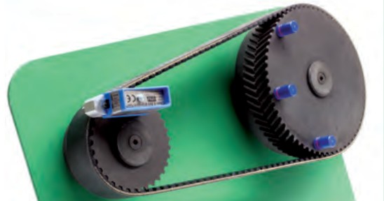
Advantages
- Longer life of belts, pulleys and bearings
- Suitable for any pulley type
- Reduced vibration
- Corrects both axial (lateral) and angular misalignment
- Lower friction and energy consumption
- Three control references for a reliable reading
Technical characteristics
| Max. recommended centre distance | 2 m (longer distances are possible, but the beam width adds to the pointing error) |
|---|---|
| Max. error | 1 mm per metre |
| Control references | 3 targets |
| Detects | Lateral (axial) misalignment and angular misalignment, horizontal and/or vertical |
Why pulley alignment matters
Any misalignment shortens belt life and causes edge wear, inconsistent belt wear and uneven load distribution. Synchronous (timing) belts are especially sensitive: their tension members are twisted multi-strand fibreglass cords with high tensile strength and very low elongation, so misalignment can lead to premature tensile failure. For synchronous drives misalignment should be limited to 1/4 degree, or 4.3 mm per metre of centre distance. Misalignment can also cause belt tracking problems; on a two-sprocket drive, belt contact with a single flange is acceptable, but contact with opposite flanges of the two sprockets should be avoided.
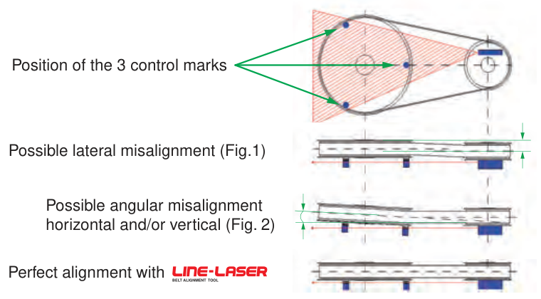
Two types of misalignment
- Lateral (offset) misalignment - the pulleys or sprockets are not located equally on their shafts (Fig. 1).
- Angular misalignment - the shafts are not parallel, horizontally and/or vertically (Fig. 2).
Misalignment can also come from incorrect bushing installation or a loose drive framework: install bushings to the pulley manufacturer's guidelines and secure the motor and framework to eliminate vibration and centre-distance fluctuation.
Care of the tool
A shock, for example an accidental fall, can affect the tool's own alignment. Check the LINE-LASER periodically on a reference surface.
Source: SIT S.p.A. catalogue "Pulleys and components", p. 166. Brand names are used for identification and technical reference.
Request a Quote Ask an Engineer All belt drive regulation products
Available on request
Specific series are being qualified with our manufacturing partners. Send your requirement and our engineers will propose a solution.
What we need to select the right product
Motor power and speed, required ratio, center distance, duty and operating hours, existing belt profile and length.
Typical applications: Fans, pumps, compressors, crushers, screens and machine drives.
Original, alternative or custom
Depending on the requirement we offer original-brand products, selected supply from qualified manufacturers, replacement solutions or custom-engineered designs. Each product shows MECHATRIC's relationship to it.
Original Brand & EquivalentSelected SupplyReplacement SolutionCustom Engineered