
Backstops & Freewheels
Engineering definition, selection, installation, maintenance & replacement guide for industrial backstops.
Industrial Backstops
Engineering support for industrial backstop selection, anti-reverse protection, low-speed shaft applications, installation review, maintenance planning, replacement and technical RFQ preparation.
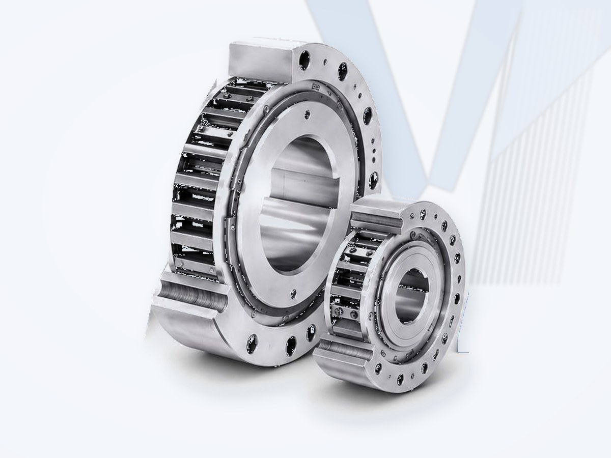
Reference Family for Engineering Comparison
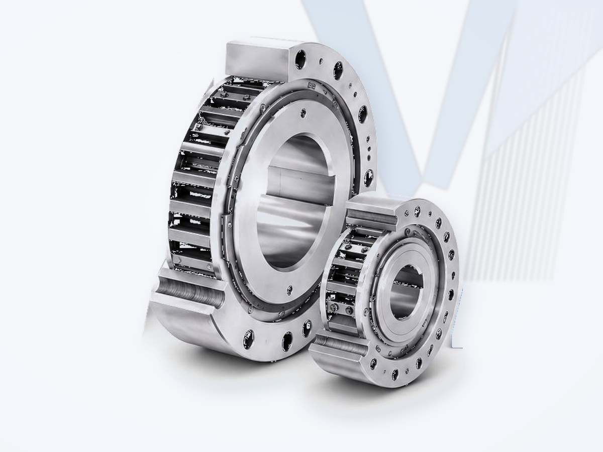
What is an industrial backstop?
An industrial backstop is a mechanical one-way device used to prevent reverse rotation of a shaft or driven machine. In normal operation it allows rotation in the designated freewheeling direction; if the machine attempts to reverse, the locking elements engage and transmit reaction torque into the supporting structure.
Backstops are used where reverse movement can create a functional or safety hazard, particularly on inclined conveyors, bucket elevators and other material-handling or process drives. They may also be described as holdbacks, anti-reverse clutches, freewheel backstops or overrunning backstops, depending on industry and design.
Important: a backstop can perform a safety-critical function. Selection must consider the actual drive, peak reverse torque, operating speed, mounting location, support arrangement, lubrication and dynamic behavior - not only shaft diameter.
What is an overrunning clutch?
An overrunning clutch (freewheel) connects two shafts so that torque is transmitted in one direction of relative rotation, while the shafts run freely in the other. Sprags or rollers wedge between inner and outer races under load. The same principle is used as a backstop (holding), an overrunning clutch (dual or creep drives) or an indexing clutch (step feeds).
How a Backstop Works
A typical sprag-type backstop contains an inner race, outer race and a cage of clamping elements. During permitted rotation the unit freewheels. When reverse rotation begins, the clamping elements engage between the races and create a torque-transmitting lock. In the RINGSPANN FRHN reference, normal backstop operation is freewheeling and locking occurs at zero speed, with immediate engagement of the clamping elements.
Main Backstop Categories
| Category | Typical engineering role |
|---|---|
| Low-speed backstop | Installed on a low-speed shaft or driven-machine shaft; commonly used for conveyors and heavy material-handling drives. |
| High-speed backstop | Installed on a higher-speed drive shaft where the selected design permits; speed, lift-off behavior and thermal conditions become especially important. |
| Torque-arm backstop | Reaction torque is transferred through an external torque arm to a suitable support structure. |
| Integrated gearbox backstop | Installed in or on a gearbox as part of the drive package; selected with gearbox ratio, shaft speed and reverse torque in mind. |
| Externally mounted freewheel/backstop | Separate shaft-mounted unit with dedicated support, retention and lubrication arrangement. |
| Special / redundant backstop system | Used where duty, risk assessment or conveyor design requires multiple devices or controlled load sharing; requires system-level engineering. |
Why Backstops Are Used
- Prevent reverse rotation: stop an inclined conveyor, elevator or driven machine from running backward after drive shutdown or loss of power.
- Protect equipment and process: reduce the risk of uncontrolled rollback and the mechanical consequences that can follow.
- Automatic mechanical action: the backstop normally freewheels and engages when reverse motion attempts to occur.
- Heavy-duty torque reaction: properly selected units can transmit substantial reverse torque into a designed support structure.
Reference Design: RINGSPANN FRHN Low-Speed Backstop
The FRHN installation and operating instructions describe a complete low-speed backstop with inner race, outer race, sprag cage, bearings, seals, cover plates, oil plugs and a torque arm, covering FRHN 700-1600 installation details. Permissible torque, permissible speed and product selection belong to the manufacturer's technical data/catalogue rather than the installation manual; MECHATRIC uses the document for application, installation, safety, maintenance and RFQ logic without publishing unsupported universal ratings.
Typical Applications & Industries
Applications: belt conveyors, bucket elevators, apron/chain conveyors, inclined material-handling systems, crushers and process drives where reverse rotation must be prevented.
Industries: mining and mineral processing, cement, steel and metals, ports and bulk handling, power generation, aggregates, fertilizer, chemical processing and heavy industry.
Engineering Selection - What Must Be Checked
| Step | Engineering check | Required data |
|---|---|---|
| 1 | Define application and consequence of reversal | Machine type, incline/load condition, process risk, required safety function and operating scenario. |
| 2 | Determine reverse / selection torque | Steady and peak reverse torque, loaded start/stop behavior, shock, dynamic amplification and manufacturer selection method. |
| 3 | Check freewheeling speed | Actual shaft speed at the backstop location and maximum permissible speed for the selected operating state. |
| 4 | Check shaft and bore interface | Shaft diameter, tolerance, key/keyway, straightness, surface condition, available mounting length and axial retention. |
| 5 | Confirm free rotation direction | Required permitted shaft direction and mounting orientation; direction must be verified before startup. |
| 6 | Design torque reaction support | Torque-arm geometry, support strength, clearances, reaction direction and freedom from harmful constraint. |
| 7 | Review bearing / external loads | Any axial or radial loads transmitted to the unit and their effect on internal bearings. |
| 8 | Check torsional behavior | Potential oscillation, repeated loading/unloading, drive transients and interaction with motor, gearbox and conveyor. |
| 9 | Check lubrication and environment | Ambient temperature, lubricant type/viscosity, contamination, storage, sealing and inspection access. |
| 10 | Verify documentation | Manufacturer rating, installation manual, drawings, maintenance requirements and project-specific safety requirements. |
Torque and Speed Are Critical Limits
The FRHN instructions warn that the maximum permissible torque must not be exceeded by application-related peak torque and that excessive speed can damage the freewheel and cause unacceptable temperature rise; selection torque is calculated using the manufacturer's catalogue.
MECHATRIC rule: do not select a backstop from nominal motor power or shaft diameter alone.
Torsional Oscillation & Dynamic Duty
Rapid repeated loading and unloading of a backstop can create severe thermal and mechanical stress. The FRHN instructions prohibit impermissible torsional oscillations that cause rapid cycling of the freewheel. High-inertia conveyors, multiple drives, long belts or unusual transients may need a system-level dynamic review.
Bearing Loads
If the installation subjects the backstop to external axial or radial loads, the internal bearings and support arrangement must be checked. A shaft-mounted unit should not be assumed to accept arbitrary external loads.
Shaft, Bore, Key & Axial Retention
Reliable backstop operation depends on a correct shaft interface. In the FRHN reference, the inner-ring bore is normally ISO H7 and the shaft ISO h6 or j6; the shaft must be straight rather than tapered and the key must not deform the inner ring. These tolerances are FRHN-specific reference data, not universal rules. The same reference uses a clearance-fit mounting with positive axial retention - the backstop must be prevented from migrating axially using the manufacturer's approved method.
Replacement warning: matching bore diameter alone is insufficient. Fit class, key geometry, axial retention, hub/inner-race length and shaft shoulder/cover arrangement must also be verified.
Free Rotation Direction
Before installation, identify the permitted freewheeling direction. The FRHN design is symmetrical and can be oriented for the required free direction; its inner race is marked with a FREE arrow, and the direction is checked and free rotation verified manually before the unit is secured. Incorrect orientation can defeat the anti-reverse function or lock the drive in the normal operating direction, so direction verification is part of MECHATRIC's installation checklist and commissioning documentation.
Torque Arm Support - A Critical Installation Detail
A torque-arm backstop transfers reverse torque to the supporting structure. The support must react the torque without rigidly constraining the backstop in a way that introduces harmful bearing loads. The FRHN instructions require the backstop head, torque-arm end and stirrup centerline to be aligned; the torque arm contacts the support in the load direction while keeping clearance on the other sides. A misaligned, twisted or rigidly held torque arm can pinch and damage the bearings.
Design principle: the torque arm is a reaction member, not a rigid mounting foot.
Installation Fundamentals
- Confirm the backstop model and application are correctly selected before installation.
- Verify free rotation direction before securing the unit.
- Do not force the backstop onto the shaft; correct shaft preparation and fit are required.
- Apply installation force only where the manufacturer permits (FRHN: on the inner-race face).
- Provide correct axial retention.
- Install and support the torque arm with the required freedom and clearance.
- Check oil/lubricant level before startup where applicable.
- Guard rotating equipment and follow site safety procedures.
Lubrication & Maintenance
Lubrication can be a primary reliability factor for backstops that use oil or grease. The FRHN reference states that lubrication maintenance is the most important single maintenance factor for long, trouble-free operation and requires oil-level verification after installation and before startup. For the FRHN family the instructions call for oil changes every 3 to 6 months, weekly oil-level checks during the first month, and later inspection based on experience but not exceeding six-month intervals; severe conditions may require more frequent maintenance. These intervals are product-specific.
Lubricant Selection (FRHN example)
| Ambient temperature | Viscosity |
|---|---|
| 0 to +50 C | ISO VG 46 / 68 |
| -15 to +15 C | ISO VG 32 |
| -40 to 0 C | ISO VG 10 |
Outside +50 C to -40 C consult the manufacturer. Always follow the current lubricant table for the exact backstop.
Important Lubrication Practices
- Do not mix incompatible oils; when changing lubricant type, follow the manufacturer's flushing procedure.
- Do not convert an oil-lubricated design to grease, or vice versa, unless the manufacturer approves it.
- Avoid unapproved solid/friction-reducing additives.
- Verify static and running oil level using the specified indicator arrangement.
- Increase inspection frequency in severe temperature, contamination, shock or high-duty service.
Storage & Long-Term Shutdown
The FRHN instructions call for protected, clean and dry storage, periodic manual rotation of the inner ring, corrosion protection of exposed surfaces and lubricant preparation before commissioning; units stored or out of service for two years or more require new seals before return to operation.
Common Failure Risks
| Risk | Possible consequence / engineering response |
|---|---|
| Undersized reverse torque rating | Loss of locking function, overheating or mechanical damage; recalculate peak/selection torque. |
| Excessive freewheeling speed | Temperature rise and internal damage; verify speed limit for operating state. |
| Wrong free direction | Incorrect operation or immediate locking; verify orientation before startup. |
| Rigid/misaligned torque arm | Bearing stress and damage; redesign support and clearances. |
| Incorrect shaft/key fit | Inner-race deformation, difficult assembly or unreliable operation; verify tolerances. |
| Poor lubrication / wrong oil | Heat, wear or malfunction; follow exact lubricant and maintenance instructions. |
| Torsional oscillation | Repeated loading/unloading, heat and possible loss of function; review drivetrain dynamics. |
How to Select an Equivalent or Replacement Backstop
A replacement backstop is evaluated as a safety-related drivetrain component. A candidate is not called equivalent merely because it fits the same shaft.
| Parameter to match | Why it matters |
|---|---|
| Application / safety function | Defines the consequence of reversal and required operating behavior. |
| Required selection / peak reverse torque | Primary locking-load criterion; include dynamic and application factors. |
| Freewheeling and maximum speed | Must be within the exact design's permissible operating range. |
| Free rotation direction | Must match the machine's required operating direction. |
| Shaft bore, fit and key | Determines correct mechanical interface without damaging the inner race. |
| Axial retention | Prevents migration of a clearance-fit unit on the shaft. |
| Torque-arm geometry and reaction point | Controls load transfer to the machine structure and bearing stress. |
| External axial/radial loads | May affect internal bearing life and allowable mounting arrangement. |
| Lubrication and ambient temperature | Determines lubricant type, viscosity and maintenance requirements. |
| Envelope / installation access | Required for physical fit, oil level access, inspection and removal. |
| Dynamic behavior | Torsional oscillation and repeated engagement can change suitability. |
| Documentation / project requirements | Safety, guarding, inspection, certification and machine-builder requirements may govern. |
MECHATRIC Interchange Classification
- Direct Interchange: all critical functional, torque, speed, shaft-interface, reaction-support and installation requirements are verified for the specific application.
- Dimensionally Compatible: the candidate fits the shaft/envelope but functional and duty verification is still required.
- Functionally Equivalent: provides the required anti-reverse function but may require changes to mounting, torque arm, lubrication or surrounding structure.
- Engineering Review Required: a potential alternative has been identified but is not yet approved as an interchange.
| Device | Primary function | Typical distinction |
|---|---|---|
| Backstop / holdback | Prevents reverse rotation. | Normally freewheels in permitted direction and locks against reverse motion. |
| Brake | Actively slows, stops or holds rotating equipment. | May require mechanical, hydraulic, pneumatic or electromagnetic actuation. |
| Overrunning clutch / freewheel | Automatically connects/disconnects based on relative rotational direction or speed. | Can be used for overrunning, indexing or backstopping depending on design. |
Information Required for Backstop Selection / RFQ
| Data group | Information to provide |
|---|---|
| Application | Conveyor, bucket elevator, crusher, gearbox or other machine; inclined/horizontal; safety function. |
| Drive system | Motor power, motor type, gearbox make/model/ratio, number of drives and drive arrangement. |
| Backstop location | Motor shaft, gearbox high/intermediate/low-speed shaft, pulley/drum shaft or driven-machine shaft. |
| Speed | Normal and maximum rpm at the backstop mounting location. |
| Torque | Calculated reverse torque, peak torque, load condition, starting/stopping behavior and dynamic factor if known. |
| Shaft interface | Shaft diameter, tolerance, key/keyway, available shaft length, shoulders and retention details. |
| Rotation | Viewed direction of normal free rotation and required anti-reverse direction. |
| Torque reaction | Existing torque arm/support dimensions, reaction direction, clearances and structural arrangement. |
| Environment | Ambient temperature, dust, moisture, corrosion, indoor/outdoor, hazardous-area considerations. |
| Lubrication | Existing oil/grease type, maintenance practice and orientation. |
| Existing unit | Manufacturer, series, size/model, nameplate, drawing, photos, failure history and installation manual if available. |
| Project requirements | Safety standard, redundancy, inspection/certification, machine-builder or end-user specification. |
Leading Manufacturers Worldwide
Well-known European, American and Asian (Japanese and Korean) manufacturers of backstops & freewheels.
| Manufacturer | Country | Product focus |
|---|---|---|
| RINGSPANN | Germany | Backstops, freewheels, brakes |
| Stieber (Regal Rexnord) | Germany | Backstops and freewheels |
| Renold | United Kingdom | Couplings, freewheels / backstops, chains |
| Regal Rexnord (Falk, Kop-Flex, Thomas, Rexnord) | USA | Grid, gear and disc couplings; gear drives; backstops; roller chain |
| Tsubaki | Japan | Couplings, POWER-LOCK, backstops, chains |
Listed for market information only. Brand names belong to their owners; their mention does not imply that MECHATRIC represents, distributes for or is authorized by these manufacturers. Product availability and equivalents are confirmed per enquiry.
MECHATRIC Engineering Support
MECHATRIC can support backstop application review, selection data preparation, torque and speed verification, shaft-interface review, torque-arm/support assessment, replacement cross-reference, maintenance planning and RFQ preparation for industrial power-transmission applications.
Engineering reference: RINGSPANN Installation and Operating Instructions for Complete Low-Speed Backstops / Complete Freewheels FRHN, E 08.788, Version 03, dated 23.05.2023. Product-specific torque ratings, speed limits, fits, lubricant requirements, maintenance intervals and installation details must be verified against current manufacturer documentation for the exact selected size and application. Backstops may perform a safety-critical function; this content supports engineering review but does not replace the manufacturer's instructions, machine risk assessment, guarding requirements or qualified installation/commissioning procedures. Brand/family names are used for technical identification and comparison only and do not imply interchangeability, authorization, representation or partnership.
Frequently Asked Questions
What is a backstop?
A one-way mechanical device that permits rotation in the normal direction and prevents reverse rotation by automatically locking.
Where are backstops commonly used?
They are particularly common on inclined conveyors, bucket elevators and other loaded drives where rollback must be prevented.
Can I select a backstop only from motor power?
No. Selection requires torque at the actual backstop shaft, peak/dynamic conditions, freewheeling speed, shaft interface, mounting arrangement and manufacturer-specific limits.
Is a backstop the same as a brake?
No. A backstop prevents reverse rotation; a brake is generally used to decelerate, stop or hold motion. Some systems require both.
Why is the torque arm important?
It transfers locking reaction torque to the machine structure. Incorrect or rigid support can impose damaging loads on the backstop bearings.
Can I replace one brand with another?
Potentially, but only after engineering review of torque, speed, shaft fit, rotation direction, reaction support, lubrication, envelope and project requirements.