
Torque Arm Gearboxes
Shaft-mounted gear reducers with torque arm for belt conveyors and industrial drives - selection, mounting, replacement and interchange.
Torque Arm Gearboxes & Shaft-Mounted Gear Reducers
Selection, mounting, replacement and interchange support for shaft-mounted speed reducers with torque arm - for belt conveyors, crushers, feeders, mixers and bulk material handling.
Engineering Reference Families
SEW-EURODRIVE F / FA / FAF
Parallel-shaft helical reducers; hollow shaft, flange and torque-arm options. K series for bevel-helical layouts.
Request a Quote →Falk Ultramite UJ / UJR
Shaft-mounted offset-helical drives (Regal Rexnord); UJR = torque-arm configuration, hollow-shaft and taper-bushing options.
Request a Quote →What is a torque arm gearbox?
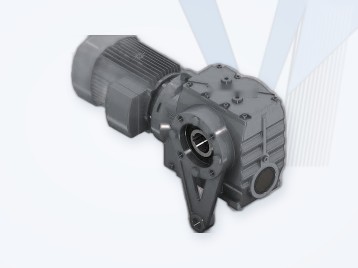
A torque arm gearbox is a shaft-mounted speed reducer whose housing is restrained against rotation by a properly engineered reaction arm. The gearbox typically mounts directly on the driven machine shaft through a hollow-shaft interface. The torque arm transmits the gearbox housing reaction to a suitable fixed structure while allowing the intended small relative movement and avoiding harmful constraint loads.
"Torque arm gearbox" describes a mounting arrangement, not a unique gear-tooth type: a shaft-mounted unit may use parallel-shaft helical, bevel-helical or other suitable reduction stages. A gearbox with a torque arm is not the same component as a conveyor backstop or holdback.
How does a torque arm gearbox work?
The electric motor drives the reducer input; the gear stages lower speed and increase output torque (subject to efficiency). The hollow output shaft drives the conveyor pulley or other machine shaft. The reaction torque that would otherwise rotate the gearbox housing is resisted by the torque arm and its anchor. In suitable designs this can eliminate a separate gearbox foundation or output coupling, but it does not eliminate the need for correct shaft support, structural design, guarding and alignment.
Basic relationships: output speed n2 = n1 / i; output torque T2 (Nm) ≈ 9550 × P2 (kW) / n2 (rpm), where P2 = P1 × total efficiency. Nominal torque alone is not a sufficient selection criterion.
Main Configurations
| Configuration | Typical characteristics / selection implications |
|---|---|
| Parallel-shaft helical, hollow shaft | Compact offset layout for conveyors, mixers and material handling; keyway, taper bushing, shrink disc or other approved connection. |
| Bevel-helical, hollow shaft | Right-angle arrangement when motor orientation or space favours a bevel-helical drive. |
| Motor-mounted gearmotor | Integrated motor adapter / motor selection; check motor poles, frequency, starting method, thermal rating and service factor. |
| Reducer with separate motor and input coupling | Greater flexibility for motor arrangement, soft-start components, maintenance and large-duty conveyor drives. |
| Single or dual torque arm arrangement | Use only manufacturer-approved geometry and load-sharing arrangement; avoid unintended housing restraint. |
| Backstop-equipped drive | Optional reverse-rotation prevention for inclined conveyors; independent verification of holding duty and direction required. |
Where Torque Arm Gearboxes Are Used
Belt conveyors and pulley drives; inclined and overland conveyors; bulk material handling; crushers and feeders; mining and mineral processing; cement plants; steelworks; aggregates and quarrying; ports; industrial mixers and rotating equipment where shaft mounting is appropriate.
Engineering Selection Procedure
| Step | Engineering input / decision |
|---|---|
| 1. Define duty | Conveyor / load type, absorbed power, starting condition, duty cycle, shock loads, reversals, daily operating hours and ambient conditions. |
| 2. Determine torque and ratio | Motor speed, required output speed, gear ratio, continuous torque, peak / start / stall torque and manufacturer-specific service factor. |
| 3. Choose gearbox topology | Parallel-shaft helical versus bevel-helical; motor-mounted versus separate drive; shaft-mounted compatibility. |
| 4. Validate hollow-shaft connection | Driven shaft OD, tolerance, material, keyway, taper bushing, shrink disc, axial retention and removal method. |
| 5. Design torque reaction | Torque arm lever length, reaction force, tension / compression, anchorage, articulation / bushings and support deflection. |
| 6. Verify structural interface | Driven shaft / bearings, housing clearance, bending loads, gearbox weight, shaft support and installation access. |
| 7. Check lubrication and thermal limits | Actual mounting position, oil level, oil type, thermal rating, cooling and breather / drain accessibility. |
| 8. Review protection and options | Backstop, brake, soft starter / VFD, torque limiter, sensors, guards and emergency-stop philosophy. |
| 9. Validate speed, efficiency and motor | Output rpm, motor frame / poles / frequency, acceleration, starting current, thermal duty and operating speed range. |
| 10. Confirm evidence | Current manufacturer drawing, rated torque, service factors, installation instructions, approvals and application-specific calculation. |
Torque Arm Design and Installation
The torque arm must carry reaction torque through a controlled load path. For an idealised single arm with perpendicular effective lever distance L (m), the approximate force is F (N) = Treaction (Nm) / L (m). Actual anchor load must account for geometry, load reversals, dynamic peaks, joint design, gravity and manufacturer instructions. Never size a reaction anchor using nominal motor torque alone.
SEW-EURODRIVE documentation specifies a torque arm option for shaft-mounted industrial gear units and explains that articulated joint-head arrangements can compensate mounting tolerances and operational offsets; its instructions emphasise locating the torque arm on the driven-machine side to reduce machine-shaft bending moments. FLENDER belt-conveyor gear unit instructions likewise warn against distortion during torque-arm mounting and show a torque arm supported on an elastic pedestal. The exact instruction is product-family-specific - use the manufacturer-approved geometry and mounting sequence for the exact unit.
Critical installation rule
Do not rigidly constrain a shaft-mounted gearbox at multiple points unless its bearing and support arrangement has been explicitly engineered. Incorrect restraint can overload output bearings and cause fretting or premature failure.
Hollow Shaft, Taper Bushing and Shrink Disc
A keyed hollow shaft uses a positive key connection; taper-bushing designs enable serviceable shaft mounting in approved sizes; shrink-disc arrangements provide a frictional interference connection with manufacturer-defined assembly torque and surface preparation. SEW TorqLOC is a proprietary hollow-shaft mounting system and must not be treated as a generic interchangeable taper bushing.
For a replacement, record the shaft outside diameter, tolerances, engagement length, key dimensions, hub shoulder, axial restraint, shaft material and dismantling clearance, and confirm whether the existing shaft can accept the candidate connection without machining. See also Shrink Discs and Taper Bushes.
Backstop vs Torque Arm - Different Functions
The torque arm resists gearbox housing reaction torque. The backstop (holdback) prevents undesired reverse rotation of a drive, typically on inclined conveyors. A backstop may be integrated in a gearbox or installed separately; it is not a substitute for a torque arm. Backstop capacity, installation direction, maximum overrunning speed and maintenance must be reviewed separately - see Backstops.
Replacement and Interchange Engineering
An interchange guide identifies potential comparison candidates; it does not establish direct drop-in equivalence. Before approval, verify ratio / output rpm, rated and peak torque, shaft connection, mounting position, torque-arm geometry, centre distances, motor frame, mass, oil configuration, thermal rating, envelope and operating conditions.
| Classification | MECHATRIC evaluation |
|---|---|
| Direct Interchange | Verified dimensions, mechanical interfaces, performance and duty support the specified replacement without adaptation. |
| Dimensionally Compatible | Physical fit appears verified; engineering performance and operating requirements still need confirmation. |
| Functionally Equivalent | Equivalent required duty with changes in mounting, shaft interface, ratio or ancillary components. |
| Engineering Review Required | A preliminary comparison exists but engineering validation and current drawings remain outstanding. |
Falk Ultramite UJ vs SEW F Series - Reference Cross-Reference
The Falk Ultramite Gearmotor Interchange and Nomenclature Guide 281-810 (2003/2007) identifies UJ as a shaft-mounted offset-helical drive. Its nomenclature distinguishes a basic housing (A), torque-arm configuration (R), hollow-shaft and taper-bushing options, gear reduction stages, mounting positions and backstop option (H). Its comparison sections reference SEW F / FA / FAF candidates at a specified reference operating point, and the guide itself warns that motor poles, gear ratio, mounting position and actual torque must be checked. The tables are useful for candidate discovery, not as present-day guarantees of identical dimensions, ratings or availability.
| Legacy reference | Engineering use - NOT an approved substitution |
|---|---|
| Falk UJ / UJR | Shaft-mounted offset-helical and torque-arm variants; inspect configuration and exact size. |
| SEW F / FA / FAF | Parallel-shaft helical reference families; inspect hollow shaft, output interface, foot / flange and torque arm. |
| Falk UW / SEW S | Helical-worm comparison in the legacy guide; a different reducer architecture from UJ / F. |
| Falk UB / SEW K | Bevel-helical comparison in the legacy guide; evaluate right-angle layout and torque-arm options. |
FLENDER and SEW - Engineering Reference Families
FLENDER: the helical and bevel-helical portfolio covers industrial applications including conveyors, bucket elevators and crushers; its belt-conveyor gearbox documentation provides practical shaft-mounting and torque-arm installation guidance. This is a reference for engineering principles, not proof that every FLENDER unit is a torque-arm gearbox.
SEW-EURODRIVE: F-series parallel-shaft helical and K-series bevel-helical reducers are relevant configurations; current X.e industrial gearbox documentation identifies /T as torque-arm mounting and differentiates output shaft arrangements. Manufacturer-specific mounting and bearing guidance governs each selected family.
MECHATRIC Engineering Support
Gearbox sizing, conveyor drive arrangement review, hollow-shaft interface checks, torque-arm reaction design review, replacement assessment, brand / model cross-reference, technical RFQs, and evaluation of gearbox, motor, brake, backstop and coupling integration.
Request for Quotation - Required Data
| Category | Required information |
|---|---|
| Application | Industry, conveyor length / incline or driven machine, load, duty cycle, environment. |
| Performance | Motor kW, poles and frequency, input rpm, output rpm, ratio, continuous / peak torque, starts per hour. |
| Gearbox | Existing brand / series / model, nameplate, serial, drawings, oil position, backstop and mounting orientation. |
| Shaft connection | Driven shaft OD / tolerance, keyway, hollow-shaft type, shrink disc / taper bushing, shaft extension. |
| Torque arm | Attachment location, lever geometry, bolt / anchor arrangement, structure stiffness and available envelope. |
| Electrical and controls | Motor type, VFD / soft starter, braking method, protection and reversing duty. |
| Replacement | Existing dimensions, photos, clearance, failure history and desired change constraints. |
Leading Manufacturers Worldwide
Well-known European, American and Asian (Japanese and Korean) manufacturers of torque arm gearboxes.
| Manufacturer | Country | Product focus |
|---|---|---|
| FLENDER | Germany | N-EUPEX, RUPEX, ELPEX, ARPEX, ZAPEX, FLUDEX couplings; industrial gear units |
| SEW-EURODRIVE | Germany | Gearmotors, industrial gear units, motors |
| NORD Drivesystems | Germany | Gearmotors and industrial gear units |
| Bonfiglioli | Italy | Gearmotors, planetary and industrial gearboxes |
| Regal Rexnord (Falk, Kop-Flex, Thomas, Rexnord) | USA | Grid, gear and disc couplings; gear drives; backstops; roller chain |
| Dodge (RBC) | USA | Gear reducers, bushings, couplings |
| Sumitomo Drive Technologies | Japan | Cyclo, gearmotors, industrial gearboxes |
Listed for market information only. Brand names belong to their owners; their mention does not imply that MECHATRIC represents, distributes for or is authorized by these manufacturers. Product availability and equivalents are confirmed per enquiry.
Need a torque arm gearbox or a replacement?
Send the nameplate, drawings and conveyor data - MECHATRIC reviews the selection, shaft connection and torque-arm reaction and prepares the RFQ.
Sources: Falk Ultramite Gearmotor Interchange and Nomenclature Guide 281-810 (legacy, 2003/2007); FLENDER helical and bevel-helical gear units and belt-conveyor gear unit instructions A5051en (06/2020); SEW-EURODRIVE X..e industrial gear units, torque arm /T, hollow-shaft mounting and TorqLOC instructions. All brand references are for technical comparison only; ratings, interfaces, availability, interchangeability and any authorization require verification for the exact model and application. MECHATRIC does not assert a manufacturer agency relationship by listing reference families.
Frequently Asked Questions
Is a torque arm gearbox a special gear type?
No. Torque arm describes the housing reaction support of a shaft-mounted reducer; internal gearing may be helical, bevel-helical or another approved type.
Can it replace a foot-mounted gearbox?
Sometimes, but the shaft / bearing arrangement, torque reaction, alignment, weight, interfaces and maintenance access must be engineered.
Is a torque arm the same as a backstop?
No. A torque arm restrains housing rotation; a backstop prevents unwanted reverse drive rotation.
Are SEW and Falk interchange sizes automatically equivalent?
No. The legacy interchange guide provides comparison candidates, not automatic fit or duty approval.
What must be checked for a conveyor retrofit?
Torque and ratio, peak loads, motor start, backstop, shaft fit, arm / anchor forces, lubrication position, thermal capacity and drawings.