
Gearmotors
Engineering definition, types, selection, replacement & drive-system integration.
Industrial Gearmotors
Engineering definition, types, selection, replacement and drive-system integration of industrial gearmotors - helical, parallel-shaft, helical-bevel, worm, planetary and servo designs.
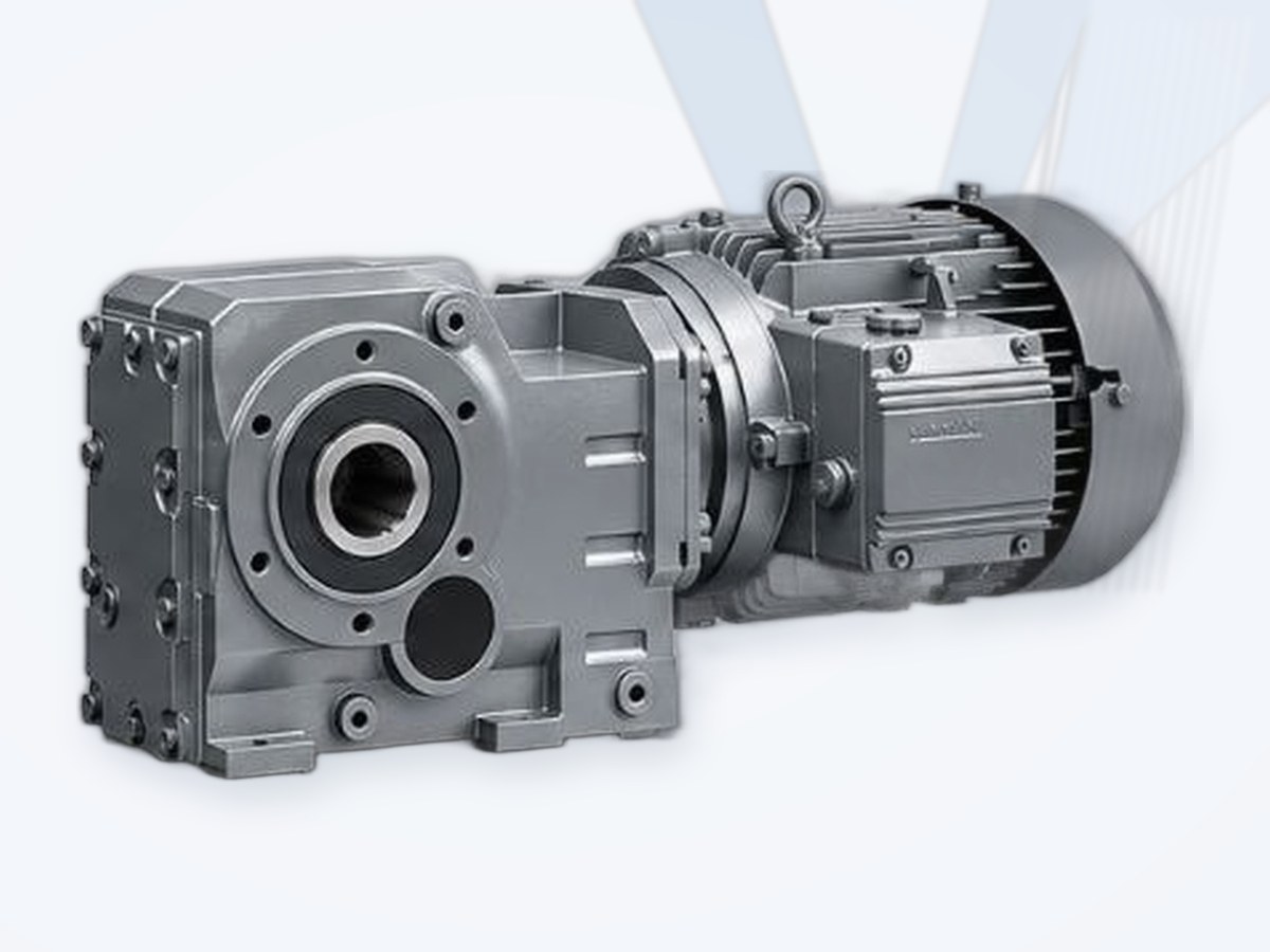
Reference Gearmotor Families
Innomotics SG / SIMOGEAR
Modular helical, parallel-shaft, bevel and worm geared motors (legacy Siemens SIMOGEAR).
Request a Quote →SEW-EURODRIVE R / F / K / S / W
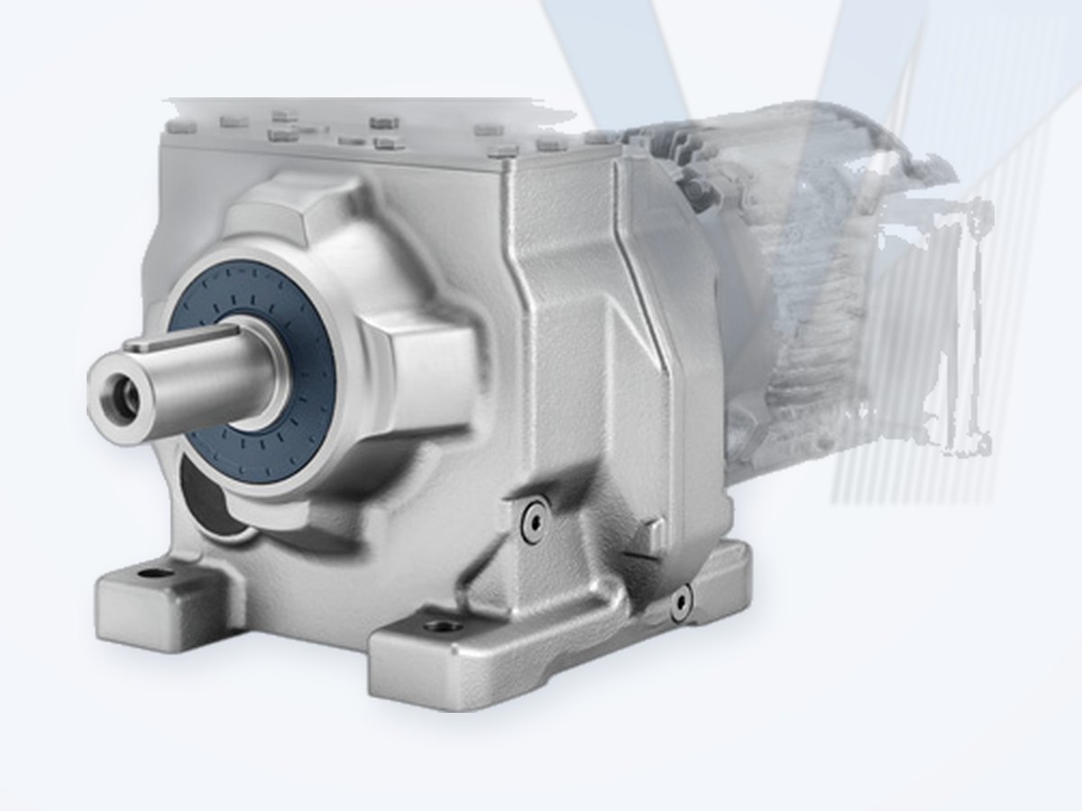
Inline, parallel-shaft, helical-bevel, helical-worm and SPIROPLAN gearmotors.
Request a Quote →Bonfiglioli C / F / A / VF-W
Inline, parallel and right-angle gearmotors with asynchronous, reluctance and servo motors.
Request a Quote →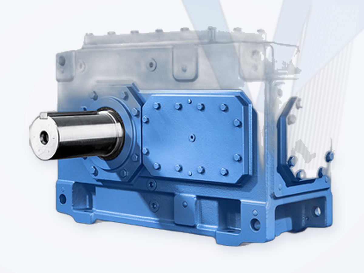
FLENDER Industrial Gear Units
Benchmark for the step from compact gearmotor to engineered heavy-duty geared drive.
Request a Quote →What is a gearmotor?
A gearmotor is a compact drive unit that combines an electric motor with a gear unit. The gearbox converts motor speed and torque to the output values required by the driven machine. In the common reduction arrangement, output speed is reduced while available output torque is increased, subject to efficiency and application limits.
A gearmotor is therefore more than a motor with a gearbox attached: the motor, gear geometry, ratio, bearings, shaft interface, mounting position, lubrication, thermal capacity, brake and inverter duty must operate as one engineered drive system. SEW-EURODRIVE describes the gearmotor as a compact unit consisting of a gear unit and motor, while current Innomotics SG material emphasizes mechanically, geometrically and thermally approved motor-gearbox combinations. These concepts form the basis of MECHATRIC's system-level selection approach.
MECHATRIC principle: select the complete drive from the application backward - required output speed, torque, duty, loads, mounting, environment and control strategy - rather than selecting the motor first and treating the gearbox as an accessory.
Main Industrial Gearmotor Types
| Type | Power flow / geometry | Typical engineering strength |
|---|---|---|
| Helical / inline | Input and output generally coaxial or parallel in an inline arrangement. | High efficiency, broad ratio range, compact general-purpose drive. |
| Parallel-shaft helical | Input and output shafts are parallel, normally offset. | Slim installation envelope, shaft-mounted options, conveyors and material handling. |
| Helical-bevel | Right-angle power flow using bevel and helical gearing. | High efficiency, high torque density, compact right-angle arrangement. |
| Helical-worm | Right-angle drive combining helical and worm stages. | Economical right-angle solution; efficiency and thermal duty require careful review. |
| Worm | Right-angle worm gear arrangement. | Compact, high ratios in limited space; efficiency, heat and duty cycle are important. |
| Planetary gearmotor | Planetary stages; inline or right-angle combinations possible. | High torque density and compactness for demanding applications. |
| Servo gearmotor | Gear unit combined with servo motor and feedback/control system. | Dynamic positioning, precision, controlled motion and low-backlash options. |
| Decentralized / inverter-integrated | Gearmotor combined with local inverter/control electronics. | Reduced cabling, distributed automation and application-specific motion control. |
Industry Reference: How Major Manufacturers Structure the Portfolio
- Innomotics SG / SIMOGEAR: helical, parallel-shaft, helical-bevel and worm-related geared-motor solutions; the current SG range is stated from 0.09 kW to 55 kW and gear-unit torque up to 19,500 Nm, with motor combinations checked for mechanical, geometric and thermal suitability.
- SEW-EURODRIVE: 2026 DRN.. gearmotor documentation structures the range around helical, parallel-shaft helical, helical-bevel, helical-worm and SPIROPLAN right-angle gearmotors, plus servo, stainless-steel, explosion-protected and other specialized configurations.
- Bonfiglioli: inline, parallel-shaft and right-angle gearboxes/gearmotors combined with asynchronous, reluctance and servo motors; the A Series is a reference for compact helical-bevel right-angle gearmotors, while planetary combinations extend torque density.
- FLENDER: primarily an industrial gear-unit benchmark rather than a compact standard gearmotor family; its helical and bevel-helical industrial gear units extend into much higher torque ranges and define the boundary between a standard gearmotor and a heavy-duty engineered geared drive.
Brand architecture note: SIMOGEAR originated as a Siemens geared-motor family. Since July 1, 2023, the relevant Low Voltage Motors business and associated product information transferred to Innomotics; legacy Siemens documentation is distinguished from current Innomotics branding.
How a Gearmotor Is Selected
The correct gearmotor is selected by translating the driven-machine requirement into output torque, output speed, ratio, motor power and mechanical/thermal service conditions.
| Step | Engineering check | Typical input data |
|---|---|---|
| 1 | Define driven machine | Conveyor, mixer, agitator, elevator, pump auxiliary, crane/travel drive, packaging machine, etc. |
| 2 | Determine required output speed | Machine speed, pulley/sprocket diameter, linear speed, process requirement. |
| 3 | Determine output torque | Steady torque, starting torque, acceleration torque, breakaway torque and peak/transient loads. |
| 4 | Determine ratio | Required output speed versus motor operating speed; consider VFD speed range. |
| 5 | Apply application/service factor | Duty, starts/hour, operating hours, shock, reversals, inertia and load spectrum. |
| 6 | Select gear type | Inline, parallel shaft, right angle, worm, planetary or servo based on efficiency, envelope and application. |
| 7 | Check motor | Power, speed, efficiency class, voltage, frequency, starting method, VFD duty and thermal margin. |
| 8 | Check output interface | Solid/hollow shaft, keyed shaft, shrink disc, flange, torque arm, sprocket/pulley and external loads. |
| 9 | Check mounting and lubrication | Mounting position affects lubrication, oil quantity, breather arrangement and sometimes thermal capacity. |
| 10 | Check environment | Ambient temperature, altitude, dust, moisture, washdown, corrosion and hazardous area. |
| 11 | Check brake/backstop/options | Holding brake, service brake, backstop, encoder, forced ventilation, heater, sensors. |
| 12 | Validate complete drive | Mechanical rating, thermal rating, bearing loads, overhung load, starts, inverter operation and dimensional fit. |
Core Speed, Ratio, Power & Torque Relationships
Gear ratio: i ≈ n1 / n2, where n1 is input/motor speed and n2 is gearbox output speed.
Power-torque: T (Nm) = 9550 x P (kW) / n (rpm).
Final selection must use the manufacturer's rated output torque, service/application factor, efficiency, thermal rating and permissible mechanical loads. Actual output speed can differ from a simple synchronous-speed calculation because motor slip, load and supply/inverter conditions influence motor operating speed.
Mechanical Selection Checks
Output torque alone is not enough:
- Radial / overhung load: belt pulleys, sprockets and external gears load the output shaft and bearings.
- Axial load: screw conveyors, vertical shafts, helical gearing and process equipment can impose thrust.
- Load position: distance from the gearbox bearing to the applied load changes bearing and shaft stress.
- Output shaft design: solid keyed, hollow, shrink disc, spline or flange changes mounting and permissible loads.
- Torque arm and shaft mounting: reaction loads and support geometry must be verified.
- Mounting position: affects oil distribution, oil quantity and sometimes permissible operating conditions.
- Backlash: material-handling drives and precision positioning drives can require very different backlash levels.
Thermal Selection & Duty Cycle
A mechanically strong gearbox can still be thermally unsuitable. Heat is generated by gear-mesh losses, bearings, seals and the motor. The thermal review becomes especially important with high ratios, worm gearing, low output speed, high ambient temperature, restricted airflow, frequent starts, cyclic overloads and inverter operation. MECHATRIC applies the same system-level principle - mechanical, geometric and thermal - for equivalent and replacement evaluation.
Motor Selection & Efficiency
| Motor parameter | Engineering question |
|---|---|
| Rated power and speed | Can the motor provide required torque across the operating speed range? |
| Voltage / frequency | Does it match the plant supply and intended connection? |
| Efficiency class | What efficiency level is required by regulation, project or lifecycle-cost target? |
| Starting method | Direct-on-line, star-delta, soft starter or VFD? |
| VFD operation | Is the motor suitable for converter duty, low-speed cooling and required speed range? |
| Brake | Holding or dynamic braking? Required brake torque and duty? |
| Encoder / feedback | Needed for speed control, positioning or closed-loop operation? |
| Forced ventilation | Needed for prolonged low-speed VFD operation or high thermal load? |
| Hazardous area | Are motor and gearbox certifications appropriate for gas/dust zone and temperature class? |
| Environment | IP protection, corrosion class, washdown, tropicalization, anti-condensation heater? |
Application-Oriented Gearmotor Selection
| Application | Typical preferred architecture | Key checks |
|---|---|---|
| Belt / roller conveyor | Helical, parallel-shaft or helical-bevel gearmotor. | Starting torque, belt load, starts/hour, shaft load, backstop, VFD speed range. |
| Bucket elevator | Helical-bevel / parallel-shaft geared drive; heavy duty may require industrial gearbox. | High starting torque, backstop, brake, service factor, thermal duty, auxiliary drive. |
| Mixer / agitator | Helical or bevel-helical; heavy duty may require industrial gearbox. | Low output speed, high torque, axial/radial shaft loads, process upset loads. |
| Crane / hoist / travel | Helical, parallel-shaft or bevel gearmotor with brake. | Brake duty, acceleration, load spectrum, starts/hour, safety requirements. |
| Intralogistics | Compact helical, parallel-shaft, bevel or decentralized gearmotor. | Energy efficiency, positioning, distributed control, compactness, noise. |
| Packaging / automation | Helical/bevel or servo gearmotor. | Dynamics, precision, backlash, encoder, inertia matching. |
| Food & beverage | Hygienic/stainless or protected gearmotor where required. | Washdown, corrosion, surface design, lubricant and hygiene requirements. |
| Heavy process industry | High-torque gearmotor or engineered industrial geared drive. | Shock, continuous duty, ambient contamination, bearing loads, serviceability. |
When a Gearmotor Is Not the Right Architecture
A compact gearmotor is not automatically the correct solution for every drive. At higher torque, power, shock loading, shaft-load or maintainability requirements, a separate industrial gearbox, motor, coupling, baseplate and auxiliary systems can be preferable. FLENDER's helical and bevel-helical industrial gearbox range illustrates this: its published nominal torque range extends from 3,100 Nm to 1,400,000 Nm with ratios from 1.25 to 450.
MECHATRIC architecture: classify the requirement first as Standard Gearmotor, High-Torque Gearmotor or Engineered Geared Drive. Do not force all applications into one product family.
Drive-System Integration
Modern gearmotor engineering increasingly includes the inverter, brake, feedback, PLC/fieldbus and condition-monitoring layer. SEW-EURODRIVE emphasizes integrated inverter and automation systems; Innomotics combines geared motors with converters, PLCs and engineering tools; Bonfiglioli offers asynchronous, reluctance and servo motors plus centralized/decentralized inverters.
Related: Electric Motors · Brakes & Backstops · Couplings · Engineering
Gearmotor Replacement & Equivalent Selection
Replacing a gearmotor requires more than matching motor power and ratio. Two drives can have the same kW and output rpm but differ materially in output torque capacity, service factor, shaft position, mounting geometry, bearing capacity, thermal rating and motor options.
| Parameter to match | Why it matters |
|---|---|
| Application and duty | Defines service factor, load spectrum, shock, starts and thermal demand. |
| Motor power / poles / operating speed | Determines input torque and speed range. |
| Gear ratio and actual output speed | Controls machine/process speed. |
| Rated and maximum output torque | Prevents mechanical under-sizing. |
| Gear type and efficiency | Affects losses, heat, size and operating cost. |
| Mounting position | Affects geometry, lubrication and installation. |
| Output shaft / hollow shaft / shrink disc | Must match driven-machine interface. |
| Flange / foot / torque-arm dimensions | Determines physical interchangeability. |
| Shaft height and center distances | Critical for drop-in replacement. |
| Overhung and axial load capacity | Critical for pulleys, sprockets, screws and vertical loads. |
| Brake / backstop | Must match holding, stopping and direction-control requirements. |
| Motor electrical data | Voltage, frequency, efficiency class, connection, VFD suitability. |
| Protection / environment | IP, corrosion, washdown, temperature and hazardous-area requirements. |
| Thermal capacity | Must remain adequate for duty cycle and ambient conditions. |
| Inverter / encoder / communication | Required for controlled or automated drives. |
MECHATRIC Interchange Classification
- Direct Interchange: mounting, shaft interface, performance, duty and relevant options are verified for the exact application.
- Dimensionally Compatible: installation dimensions/interfaces are compatible, but mechanical, thermal or electrical suitability still needs confirmation.
- Functionally Equivalent: required function and performance can be achieved, but adaptation of mounting, shaft, motor, brake or controls may be required.
- Engineering Review Required: candidate alternative identified; approval awaits sufficient technical evidence.
Replacement rule: "same kW + same rpm" is not proof of interchangeability.
| Manufacturer / family | Useful reference point |
|---|---|
| Innomotics SG / legacy Siemens SIMOGEAR | Modular helical, parallel-shaft, bevel and worm-related geared-motor systems; integrated configuration and automation context. |
| SEW-EURODRIVE R / F / K / S / W | Broad modular reference covering inline, parallel-shaft and right-angle industrial gearmotors. |
| Bonfiglioli C / F / A / VF-W and planetary | Inline, parallel and right-angle architectures with multiple motor technologies. |
| FLENDER industrial gear units | Benchmark for the transition from compact gearmotor to high-torque engineered geared-drive architecture. |
Information Required for Gearmotor Selection / RFQ
| Data group | Information to provide |
|---|---|
| Driven machine | Application, machine type, operating cycle and criticality. |
| Power / torque | Required output torque, motor power if known, starting/peak torque and load spectrum. |
| Speed | Required output rpm, motor/base speed and required variable-speed range. |
| Existing drive | Manufacturer, series/type code, complete nameplate, ratio, output rpm, service factor. |
| Mounting | Foot/flange/shaft mounted, mounting position, torque arm and available envelope. |
| Output interface | Solid/hollow shaft, diameter, key, spline, shrink disc, flange and shaft direction. |
| External loads | Pulley/sprocket diameter, radial load position, axial load and direction. |
| Motor electrical | Voltage, frequency, efficiency class, starting method, VFD and control requirements. |
| Options | Brake, backstop, encoder, forced fan, heater, sensors, special bearings, low backlash. |
| Environment | Ambient temperature, altitude, dust, humidity, washdown, corrosion and hazardous area. |
| Documents | Nameplate photo, dimensional drawing, machine drawing, existing catalog page and site photographs. |
Leading Manufacturers Worldwide
Well-known European, American and Asian (Japanese and Korean) manufacturers of gearmotors.
| Manufacturer | Country | Product focus |
|---|---|---|
| SEW-EURODRIVE | Germany | Gearmotors, industrial gear units, motors |
| NORD Drivesystems | Germany | Gearmotors and industrial gear units |
| Innomotics (former Siemens motors) | Germany | SIMOTICS / SG motors and geared motors |
| Bonfiglioli | Italy | Gearmotors, planetary and industrial gearboxes |
| Regal Rexnord (Falk, Kop-Flex, Thomas, Rexnord) | USA | Grid, gear and disc couplings; gear drives; backstops; roller chain |
| Dodge (RBC) | USA | Gear reducers, bushings, couplings |
| Sumitomo Drive Technologies | Japan | Cyclo, gearmotors, industrial gearboxes |
| Nidec | Japan | Industrial motors and drives |
Listed for market information only. Brand names belong to their owners; their mention does not imply that MECHATRIC represents, distributes for or is authorized by these manufacturers. Product availability and equivalents are confirmed per enquiry.
MECHATRIC Engineering Support
MECHATRIC supports industrial customers with application review, gearmotor type selection, output torque and speed definition, service-factor review, motor and VFD integration, mounting/interface review, brake and backstop selection, replacement cross-reference and engineering evaluation of alternative drive solutions.
Sources reviewed: innomotics.com (SG geared motors), Siemens legacy SIMOGEAR documentation, sew-eurodrive.com (2026 DRN.. gearmotors), bonfiglioli.com and flender.com. Manufacturer-specific ratings and claims are reference examples, not universal MECHATRIC specifications. Exact torque, ratio, power, speed, efficiency, service factor, overhung load, thermal rating, dimensions, certification and interchangeability must be verified against the current documentation for the exact manufacturer, series, size, motor and mounting configuration. Brand/family names are used for technical identification and comparison and do not imply representation, authorization or commercial partnership.
Frequently Asked Questions
What is the difference between a gearbox and a gearmotor?
A gearbox is the mechanical speed/torque conversion unit. A gearmotor integrates a motor and gearbox as a matched drive assembly.
Which gearmotor type is most efficient?
Efficiency depends on architecture and operating point. Helical and helical-bevel stages are generally strong choices where high efficiency is important; worm-based solutions require closer efficiency and thermal review.
How do I calculate gearmotor output torque?
Use power, speed and efficiency for preliminary calculation, then verify the manufacturer's rated output torque and application/service factor.
Can I replace a SEW gearmotor with Innomotics or Bonfiglioli?
Potentially, but only after mechanical, dimensional, thermal, electrical and duty compatibility are verified. Brand-to-brand equivalence is not established by kW and ratio alone.
Is SIMOGEAR a Siemens or Innomotics product?
SIMOGEAR originated under Siemens. Official documentation states that the relevant Low Voltage Motors business and product information transferred to Innomotics from July 1, 2023. Current sourcing and documentation should therefore be checked under Innomotics.
When should I use an industrial gearbox instead of a gearmotor?
When torque, power, shock, shaft loads, serviceability, auxiliary systems or project architecture exceed the practical range of a compact modular gearmotor.