
QD Bushings & Hubs (DODGE QD)
Flanged quick-detachable tapered bushings with 4-degree taper, conventional or reverse mounting, sizes QT to S, and matching QD hubs.
QD Bushings & Hubs
Flanged, split quick-detachable (QD) bushings with a 4-degree taper for mounting sheaves, sprockets, couplings and other hubs on shafts - conventional or reverse mounting, sizes QT to S, finished bores in inch and metric, reborable bushings and matching weld-on hubs. Reference: DODGE PT6 catalogue.
What is a QD bushing?
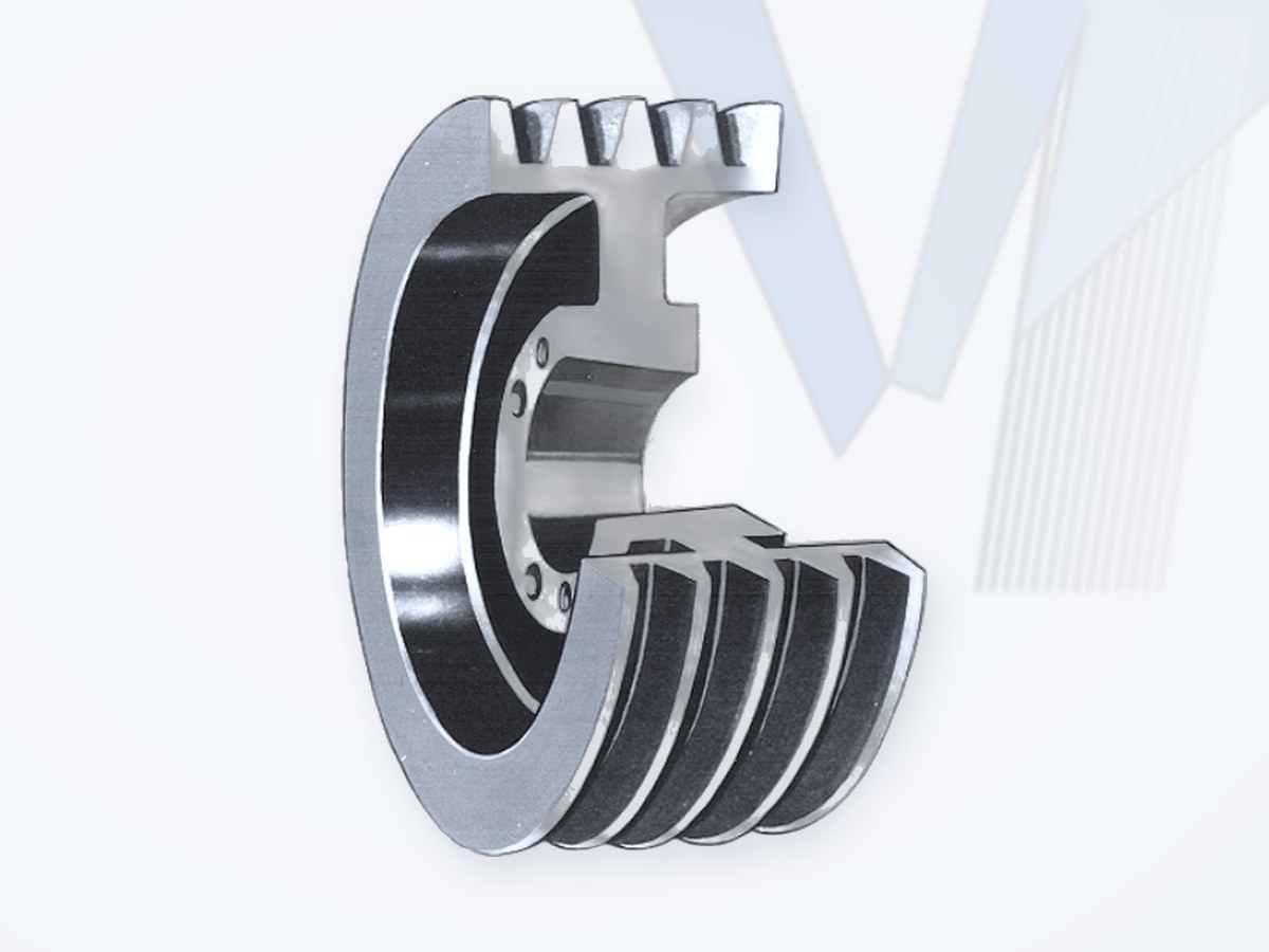
A QD (quick-detachable) bushing is a flanged, split tapered bushing. The bushing bore fits the shaft (usually with a key), while its 4-degree tapered outside fits the matching tapered bore of the hub. Cap screws through the flange pull the hub onto the taper; the split closes onto the shaft and clamps the assembly. For removal the same screws are moved into jackscrew holes and push the hub off the taper.
Unlike a flush-mounted Taper-Lock type bushing, the QD flange stands outside the hub, so flange clearance must be checked. The hub must match the QD size - a QD bushing does not fit a Taper-Lock hub.
Features
- 4-degree taper; split, flanged design.
- Easy on / easy off with the same cap screws used as jackscrews.
- Conventional or reverse mounting (reverse mounting also for sizes M to W in the DODGE range).
- Finished bores in popular sizes plus minimum-plain-bore bushings for custom reboring (rebored bushings must be saw-split after reboring).
- Metric-bore QD bushings with metric hardware available.
- Matching QD hubs, including weld-on hubs for conveyor pulleys.
QD Bushing Ratings & Bore Range
| Size | Torque capacity (lb-in) | Torque capacity (Nm, approx.) | Bore range, full keyway (in) | Max. bore, shallow keyway (in) | Max. bore, no keyway (in) |
|---|---|---|---|---|---|
| QT | 1,000 | 113 | 3/8 - 1-1/4 | 1-1/2 | 1-9/16 |
| JA | 1,000 | 113 | 1/2 - 1 | 1-3/16 | 1-1/4 |
| SH | 3,500 | 396 | 1/2 - 1-3/8 | 1-5/8 | 1-11/16 |
| SDS | 5,000 | 565 | 1/2 - 1-5/8 | 1-15/16 | 2 |
| SD | 5,000 | 565 | 1/2 - 1-5/8 | 1-15/16 | 2 |
| SK | 7,000 | 791 | 1/2 - 2-1/8 | 2-1/2 | 2-5/8 |
| SF | 11,000 | 1,243 | 1/2 - 2-5/16 | 2-15/16 | - |
| E | 20,000 | 2,260 | 7/8 - 2-7/8 | 3-1/2 | - |
| F | 30,000 | 3,390 | 1 - 3-1/4 | 3-15/16 | 4 |
| J | 45,000 | 5,085 | 1-1/2 - 3-3/4 | 4-1/2 | - |
| M | 85,000 | 9,605 | 2 - 4-3/4 | 5-1/2 | - |
| N | 150,000 | 16,950 | 2-7/16 - 5 | 6 | - |
| P | 250,000 | 28,250 | 2-15/16 - 5-15/16 | 7 | - |
| W | 375,000 | 42,375 | 4 - 7-1/2 | 8-1/2 | - |
| S | 625,000 | 70,625 | 5-1/2 - 9 | 10 | - |
Torque ratings apply when the bushing installation screws are tightened to the catalogue torque. Do not over-torque the screws - this can damage the hub. Hub material and hub dimensions must suit the selected size.
Conventional and Reverse Mounting
| Step | Conventional mounting | Reverse mounting |
|---|---|---|
| 1 | Place bushing in product (hub) | Place bushing in product (hub) |
| 2 | Align clearance holes in the product with threaded holes in the bushing | Align clearance holes in the bushing with threaded holes in the product |
| 3 | Install screws and lock washers finger tight | Install screws and lock washers finger tight |
| 4 | Slide assembly onto shaft, flange first | Slide assembly onto shaft, flange outward |
| 5 | Locate for drive alignment; tighten cap screws alternately and evenly to the specified torque | Locate for drive alignment; tighten cap screws alternately and evenly to the specified torque |
| Removal | Move cap screws into the threaded holes of the product and tighten alternately until the grip releases | Move cap screws into the threaded holes of the bushing flange and tighten alternately until the grip releases |
Important
Do not use lubricants or anti-seize compounds on tapered bore or bushing surfaces. Check wrench clearance for installation and removal, especially in reverse mounting.
Selection & Replacement Checks
- Shaft diameter, keyway (full, shallow or none) and tolerance.
- Transmitted torque including service factor - compare with the size rating.
- Hub: QD size, material (cast iron or steel), hub diameter, mounting direction and available clearance.
- Existing bushing marking (size and bore) and cap screw size.
- QD sizes from different makers share the industry nomenclature, but dimensions, ratings and hub fit must be verified before replacement.
Replacement & Interchange Classification
| Classification | Meaning |
|---|---|
| Direct Interchange | Fully verified |
| Dimensionally Compatible | Dimensional checks passed, performance still to verify |
| Functionally Equivalent | Different design meeting validated application requirements |
| Engineering Review Required | Insufficient evidence or modifications needed |
Need QD bushings or hubs?
Send the bushing size and bore, keyway, quantity and the sheave / sprocket it is used with - MECHATRIC checks the fit and prepares the RFQ.
Source: DODGE, PT Component Quick References - Bushings and Hubs (PT6). QD is a registered trademark of Emerson Electric; TAPER-LOCK and GRIP-TIGHT are trademarks of their owners. Data in inches and lb-in as published; Nm values are converted (1 lb-in = 0.113 Nm) and rounded. Brand names are used for technical identification only; MECHATRIC does not represent DODGE and supplies original or equivalent parts after dimensional and rating check. Always confirm current manufacturer data and installation instructions.
Frequently Asked Questions
Can a QD bushing replace a Taper-Lock bushing?
Not directly. The taper (4 degrees vs 8 degrees), flange, screw pattern and hub bore differ; the hub must be changed as well.
What is the difference between conventional and reverse mounting?
In conventional mounting the bushing flange faces the shaft end / motor side and screws pass through the hub; in reverse mounting the flange faces outward and screws pass through the bushing flange. The choice depends on access and clearance.
Can a QD bushing be rebored?
Yes, plain-bore bushings are made for reboring; after reboring the bushing must be saw-split before use.