
MECHATRIC Coupling Academy
Rotor & Coupling Balancing – ISO 1940-1 Masterclass
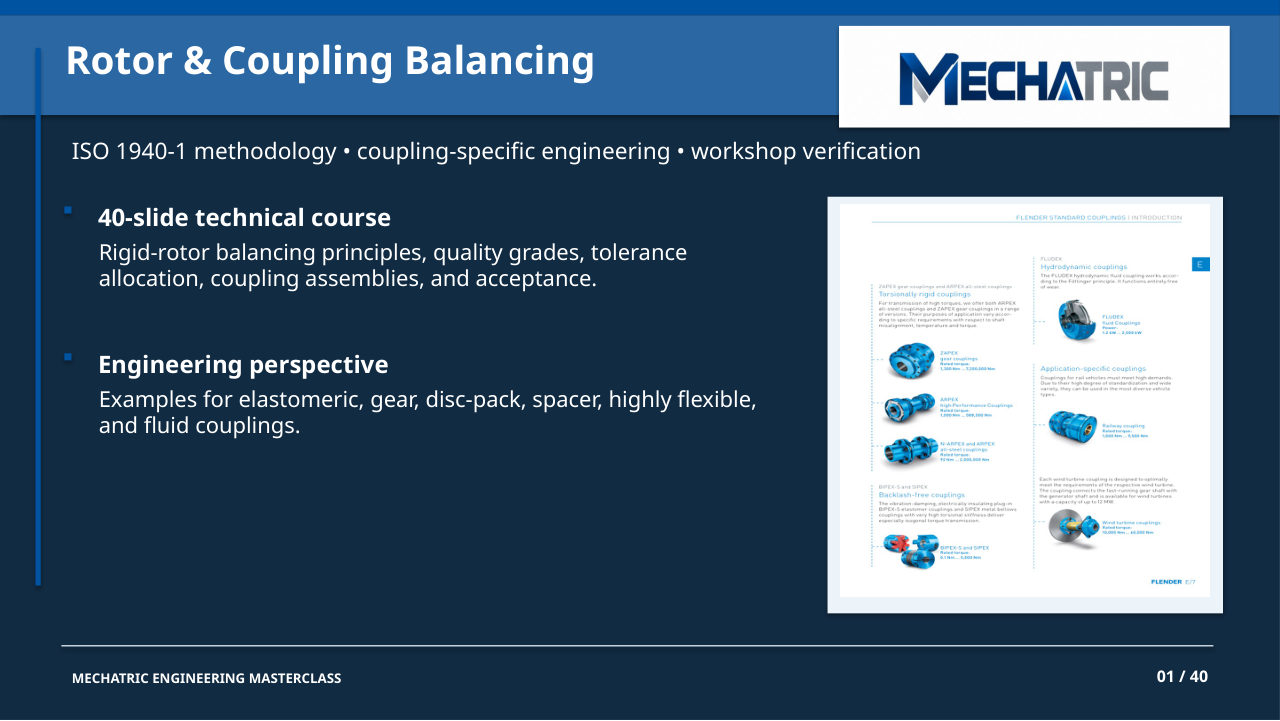
40-slide course on rigid-rotor balancing for couplings: static, couple and dynamic unbalance, ISO 1940-1 balance grades, permissible residual unbalance, plane allocation, key convention, worked examples and workshop verification.

Swipe or use the arrows
Presentation Outline
Key points of each slide – a quick engineering reference.
Balancing Engineering
Learning objectives
- What participants will be able to calculate and specify
- Explain static, couple and dynamic unbalance in rigid rotors.
- Calculate permissible residual unbalance from grade G, mass and maximum service speed.
- Select appropriate balance planes, key convention, verification and documentation.
- Translate rotor criteria into coupling procurement and assembly practice.
Sources & Limitations
Source hierarchy and scope
- Interpretation must respect document applicability
- ISO 1940-1:2003
- Rigid-state rotors: balance tolerances, plane allocation and verification. Not a flexible-rotor balancing procedure.
- IRD Balancing technical paper
- Practical tutorial and allocation examples; secondary guidance, not a substitute for the standard.
- FLENDER FLE 10 introduction
- Coupling families, balancing conventions, proprietary balancing options and application guidance.
Coupling Taxonomy
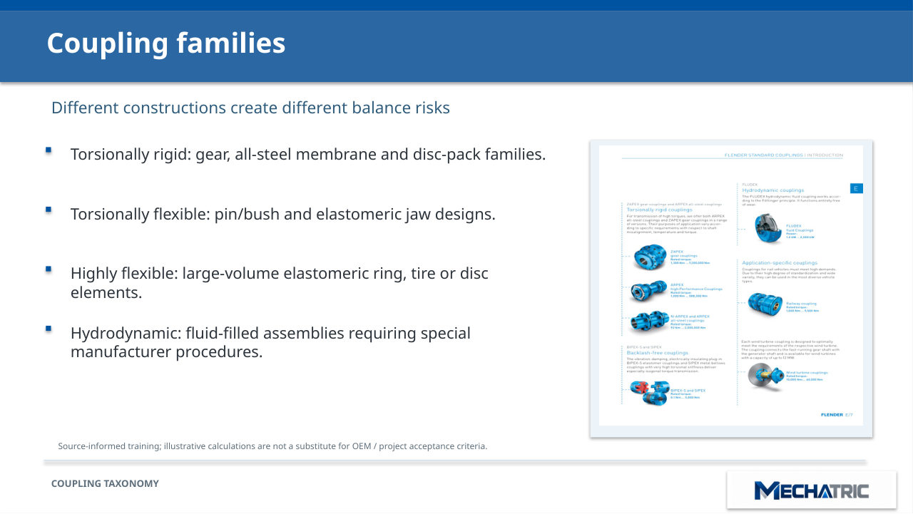
Coupling families
- Different constructions create different balance risks
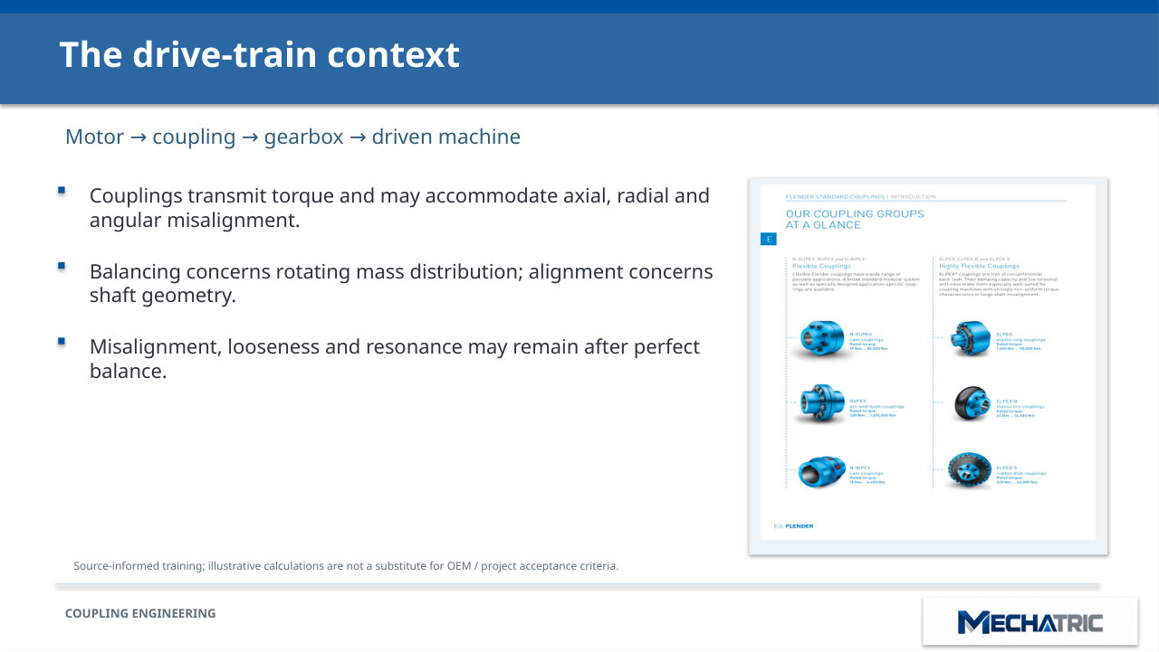
- Torsionally rigid: gear, all-steel membrane and disc-pack families.
- Torsionally flexible: pin/bush and elastomeric jaw designs.
- Highly flexible: large-volume elastomeric ring, tire or disc elements.
- Hydrodynamic: fluid-filled assemblies requiring special manufacturer procedures.
- Source-informed training; illustrative calculations are not a substitute for OEM / project acceptance criteria.
Balancing Engineering
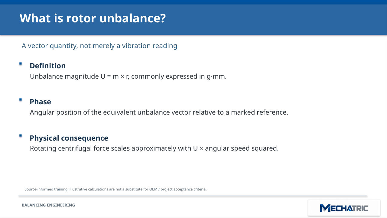
What is rotor unbalance?
- A vector quantity, not merely a vibration reading
- Definition
- Unbalance magnitude U = m × r, commonly expressed in g·mm.
- Phase
- Angular position of the equivalent unbalance vector relative to a marked reference.
- Physical consequence
- Rotating centrifugal force scales approximately with U × angular speed squared.
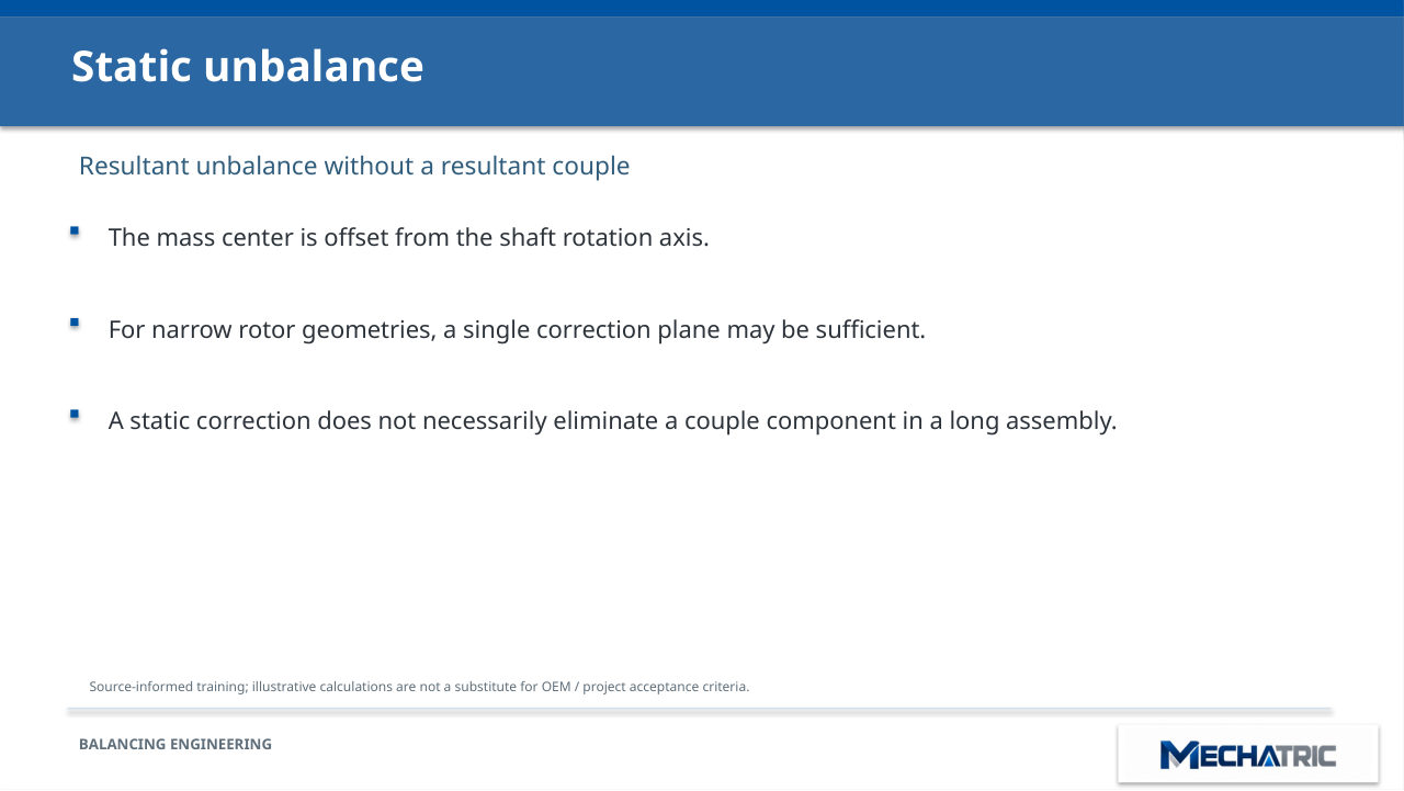
Static unbalance
- Resultant unbalance without a resultant couple
- The mass center is offset from the shaft rotation axis.
- For narrow rotor geometries, a single correction plane may be sufficient.
- A static correction does not necessarily eliminate a couple component in a long assembly.
- Source-informed training; illustrative calculations are not a substitute for OEM / project acceptance criteria.
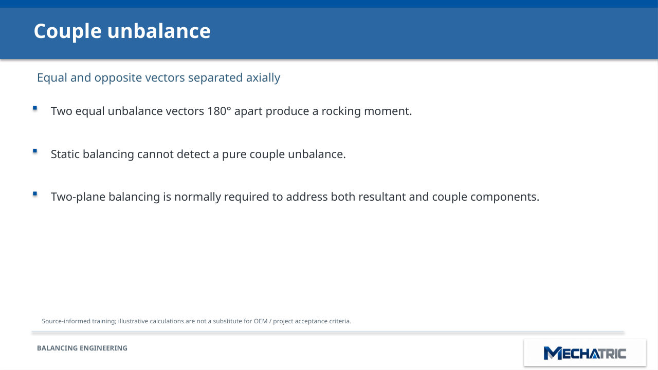
Couple unbalance
- Equal and opposite vectors separated axially
- Two equal unbalance vectors 180° apart produce a rocking moment.
- Static balancing cannot detect a pure couple unbalance.
- Two-plane balancing is normally required to address both resultant and couple components.
- Source-informed training; illustrative calculations are not a substitute for OEM / project acceptance criteria.
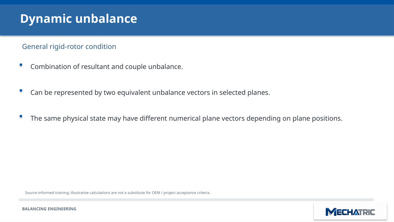
Dynamic unbalance
- General rigid-rotor condition
- Combination of resultant and couple unbalance.
- Can be represented by two equivalent unbalance vectors in selected planes.
- The same physical state may have different numerical plane vectors depending on plane positions.
- Source-informed training; illustrative calculations are not a substitute for OEM / project acceptance criteria.
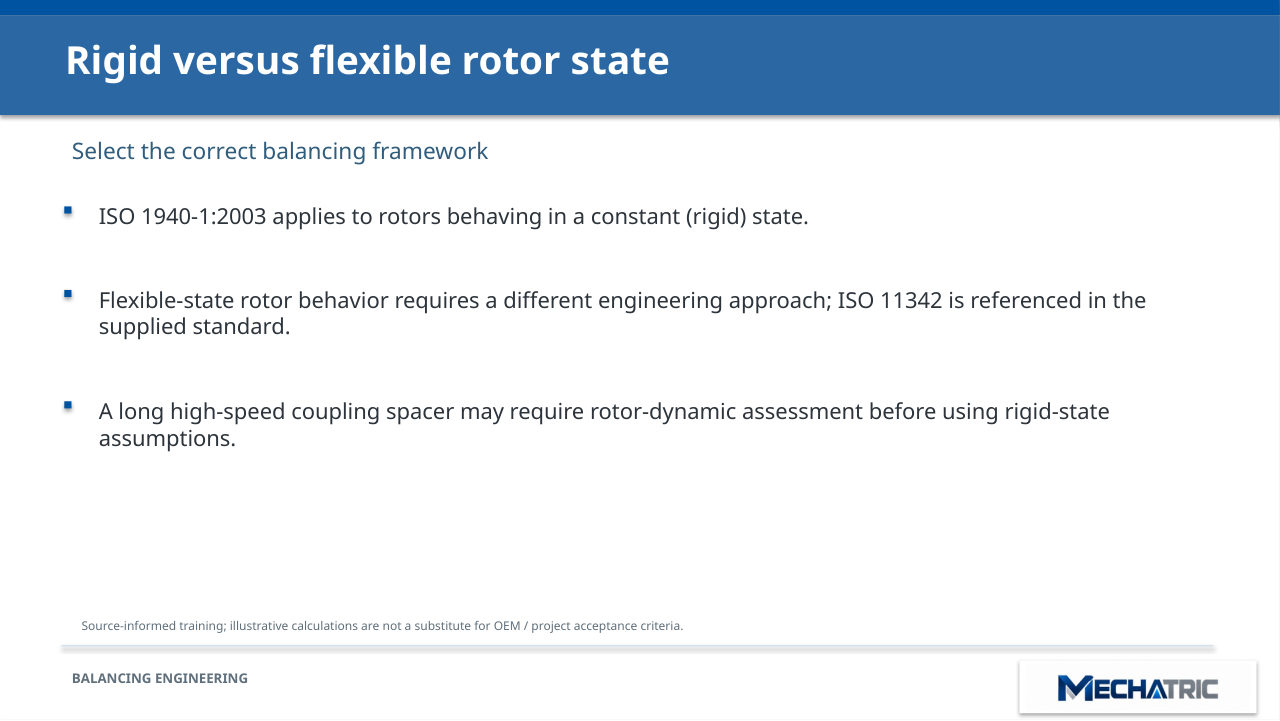
Rigid versus flexible rotor state
- Select the correct balancing framework
- ISO 1940-1:2003 applies to rotors behaving in a constant (rigid) state.
- Flexible-state rotor behavior requires a different engineering approach; ISO 11342 is referenced in the supplied standard.
- A long high-speed coupling spacer may require rotor-dynamic assessment before using rigid-state assumptions.
- Source-informed training; illustrative calculations are not a substitute for OEM / project acceptance criteria.
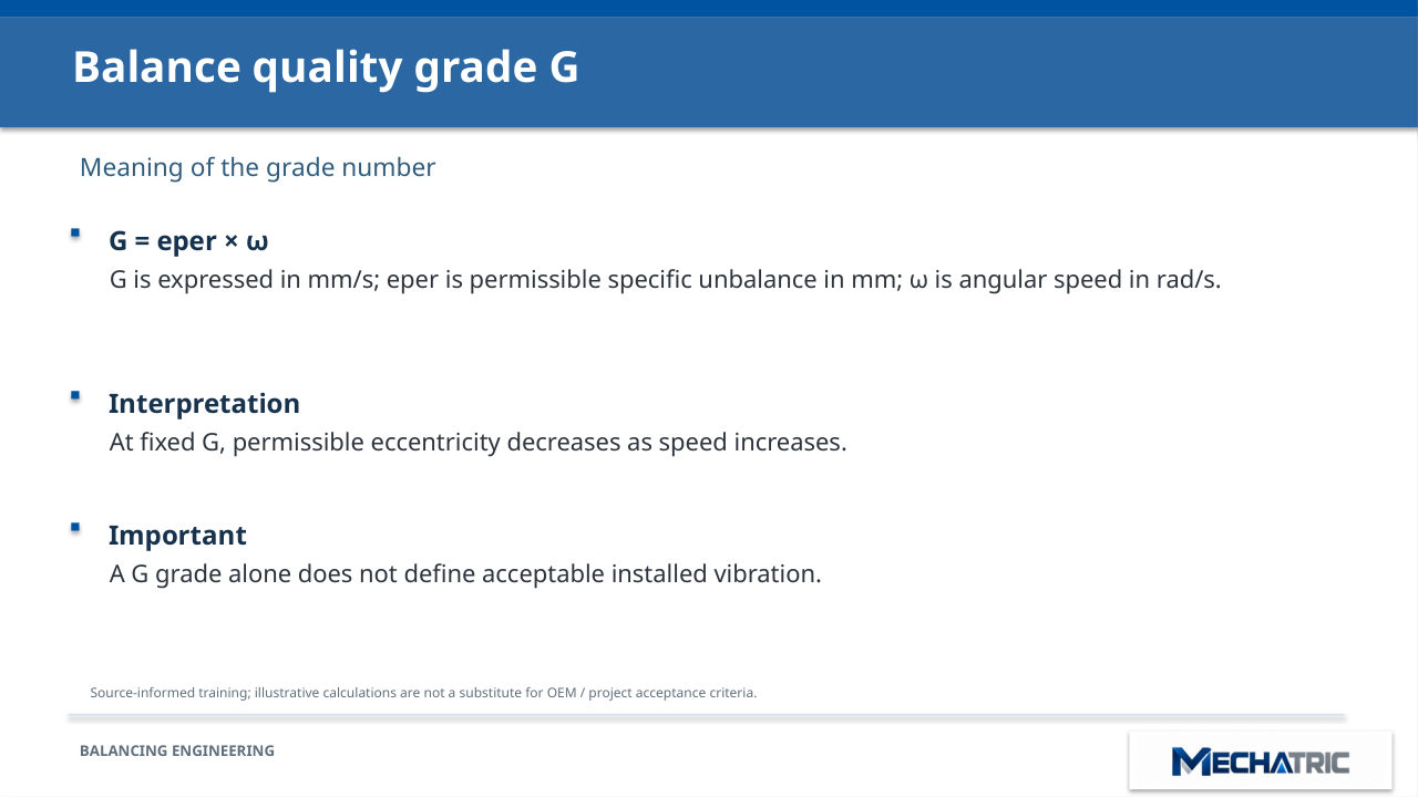
Balance quality grade G
- Meaning of the grade number
- G = eper × ω
- G is expressed in mm/s; eper is permissible specific unbalance in mm; ω is angular speed in rad/s.
- Interpretation
- At fixed G, permissible eccentricity decreases as speed increases.
- Important
- A G grade alone does not define acceptable installed vibration.
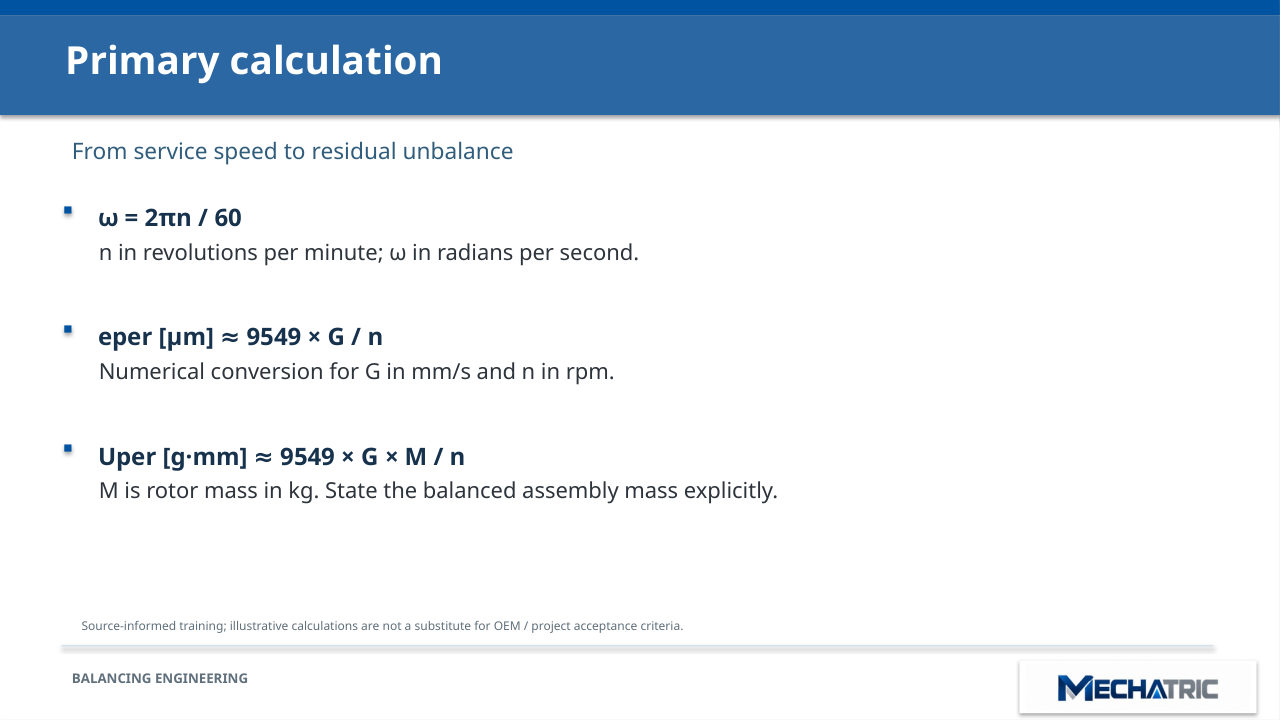
Primary calculation
- From service speed to residual unbalance
- ω = 2πn / 60 n in revolutions per minute; ω in radians per second. eper [µm]
- 9549 × G / n
- ≈
- Numerical conversion for G in mm/s and n in rpm.
- Uper [g·mm]
- 9549 × G × M / n
Quality Grade Selection
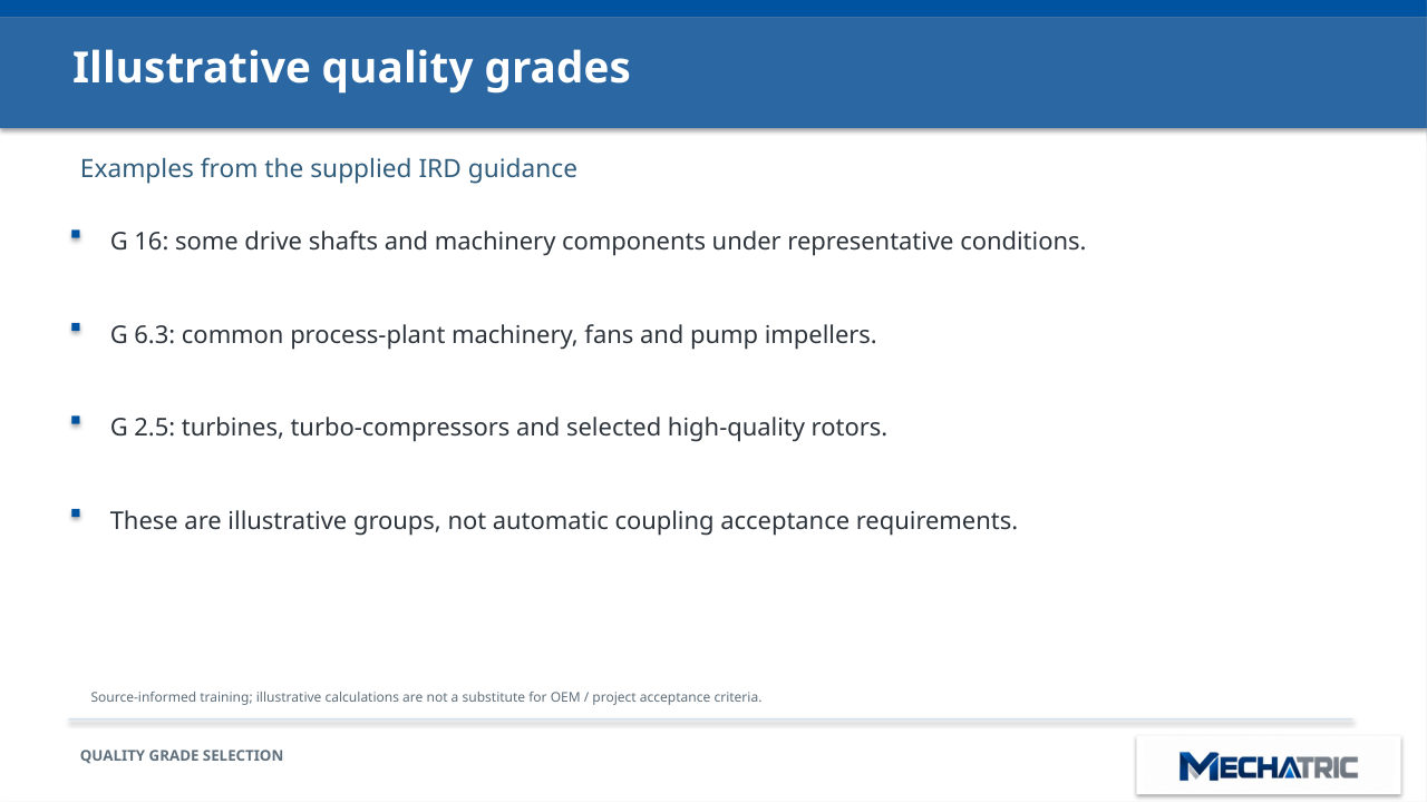
Illustrative quality grades
- Examples from the supplied IRD guidance
- G 16: some drive shafts and machinery components under representative conditions.
- G 6.3: common process-plant machinery, fans and pump impellers.
- G 2.5: turbines, turbo-compressors and selected high-quality rotors.
- These are illustrative groups, not automatic coupling acceptance requirements.
- Source-informed training; illustrative calculations are not a substitute for OEM / project acceptance criteria.
Flender Application Guidance
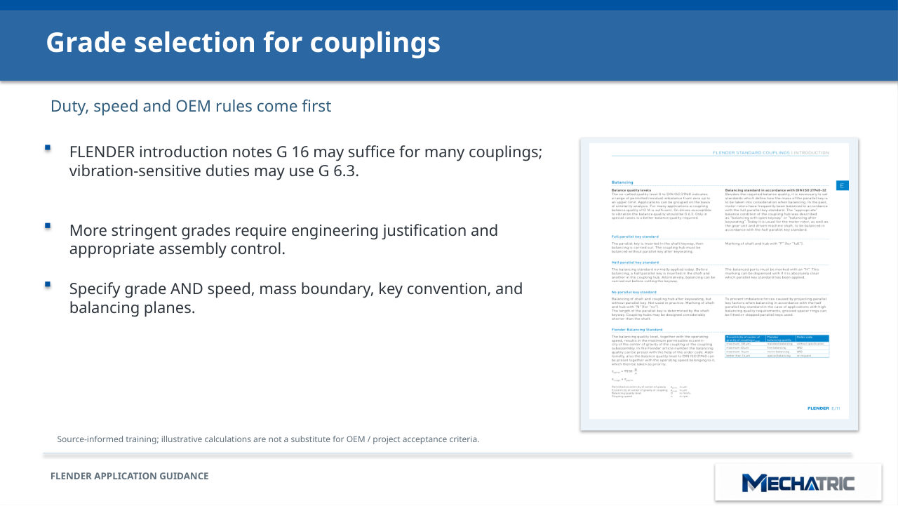
Grade selection for couplings
- Duty, speed and OEM rules come first
- FLENDER introduction notes G 16 may suffice for many couplings; vibration-sensitive duties may use G 6.3.
- More stringent grades require engineering justification and appropriate assembly control.
- Specify grade AND speed, mass boundary, key convention, and balancing planes.
- Source-informed training; illustrative calculations are not a substitute for OEM / project acceptance criteria.
Balancing Engineering
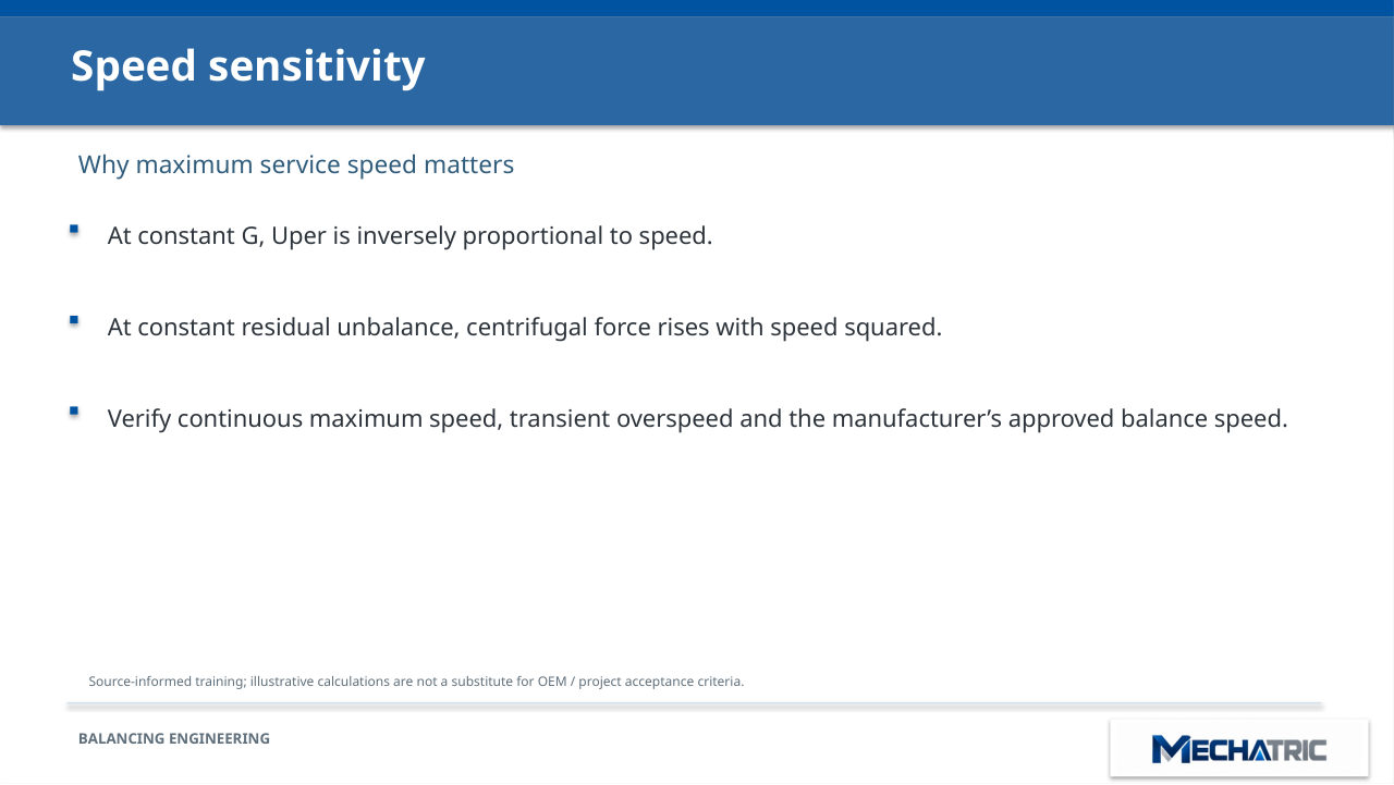
Speed sensitivity
- Why maximum service speed matters
- At constant G, Uper is inversely proportional to speed.
- At constant residual unbalance, centrifugal force rises with speed squared.
- Verify continuous maximum speed, transient overspeed and the manufacturer’s approved balance speed.
- Source-informed training; illustrative calculations are not a substitute for OEM / project acceptance criteria.
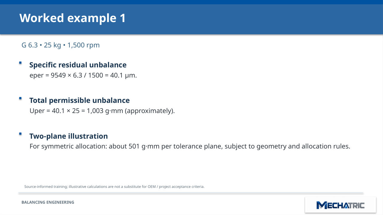
Worked example 1
- G 6.3 • 25 kg • 1,500 rpm
- Specific residual unbalance eper = 9549 × 6.3 / 1500 = 40.1 µm.
- Total permissible unbalance
- Uper = 40.1 × 25 = 1,003 g·mm (approximately).
- Two-plane illustration
- For symmetric allocation: about 501 g·mm per tolerance plane, subject to geometry and allocation rules.
- Source-informed training; illustrative calculations are not a substitute for OEM / project acceptance criteria.
Worked example 2
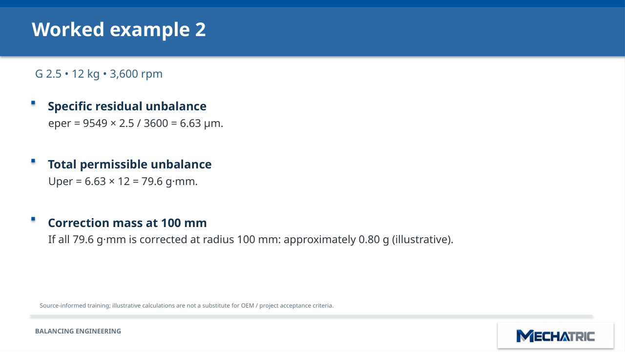
- G 2.5 • 12 kg • 3,600 rpm
- Specific residual unbalance eper = 9549 × 2.5 / 3600 = 6.63 µm.
- Total permissible unbalance
- Uper = 6.63 × 12 = 79.6 g·mm.
- Correction mass at 100 mm
- If all 79.6 g·mm is corrected at radius 100 mm: approximately 0.80 g (illustrative).
- Source-informed training; illustrative calculations are not a substitute for OEM / project acceptance criteria.
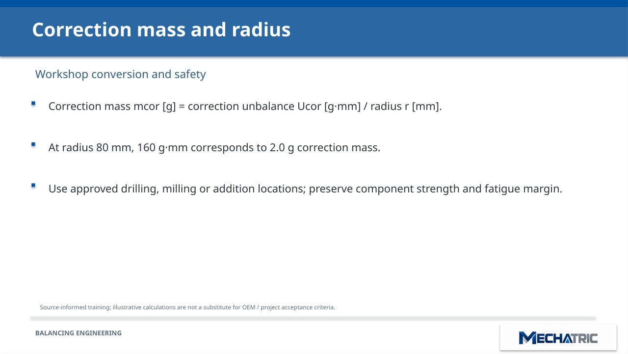
Correction mass and radius
- Workshop conversion and safety
- Correction mass mcor [g] = correction unbalance Ucor [g·mm] / radius r [mm].
- At radius 80 mm, 160 g·mm corresponds to 2.0 g correction mass.
- Use approved drilling, milling or addition locations; preserve component strength and fatigue margin.
- Source-informed training; illustrative calculations are not a substitute for OEM / project acceptance criteria.
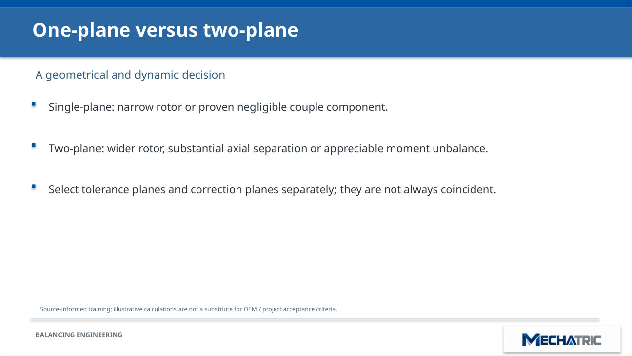
One-plane versus two-plane
- A geometrical and dynamic decision
- Single-plane: narrow rotor or proven negligible couple component.
- Two-plane: wider rotor, substantial axial separation or appreciable moment unbalance.
- Select tolerance planes and correction planes separately; they are not always coincident.
- Source-informed training; illustrative calculations are not a substitute for OEM / project acceptance criteria.
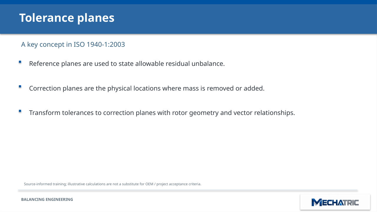
Tolerance planes
- A key concept in ISO 1940-1:2003
- Reference planes are used to state allowable residual unbalance.
- Correction planes are the physical locations where mass is removed or added.
- Transform tolerances to correction planes with rotor geometry and vector relationships.
- Source-informed training; illustrative calculations are not a substitute for OEM / project acceptance criteria.
Tolerance Allocation
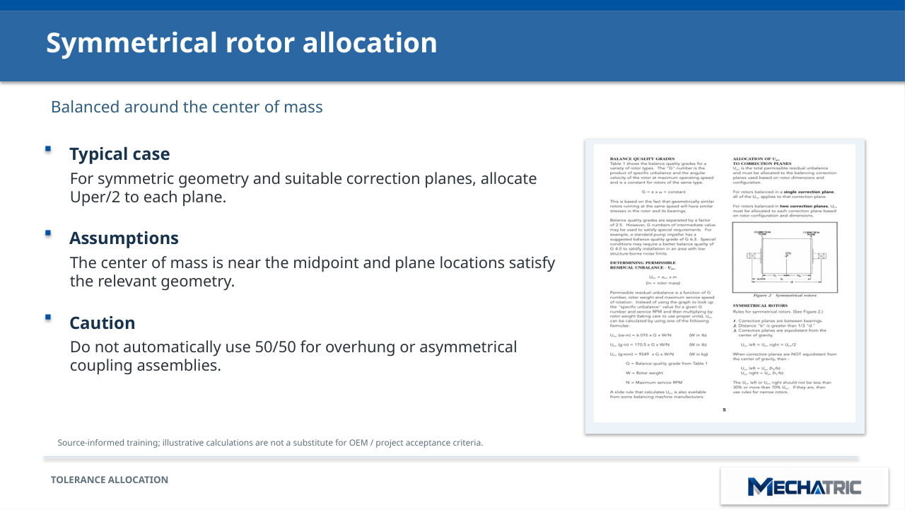
Symmetrical rotor allocation
- Balanced around the center of mass
- Typical case
- For symmetric geometry and suitable correction planes, allocate
- Uper/2 to each plane.
- Assumptions
- The center of mass is near the midpoint and plane locations satisfy the relevant geometry.
- Caution
Balancing Engineering
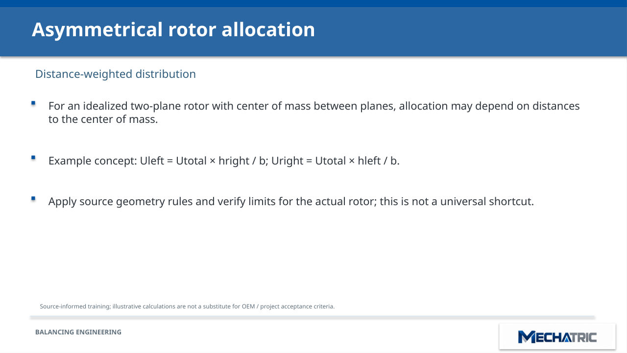
Asymmetrical rotor allocation
- Distance-weighted distribution
- For an idealized two-plane rotor with center of mass between planes, allocation may depend on distances to the center of mass.
- Example concept: Uleft = Utotal × hright / b; Uright = Utotal × hleft / b.
- Apply source geometry rules and verify limits for the actual rotor; this is not a universal shortcut.
- Source-informed training; illustrative calculations are not a substitute for OEM / project acceptance criteria.
Tolerance Allocation
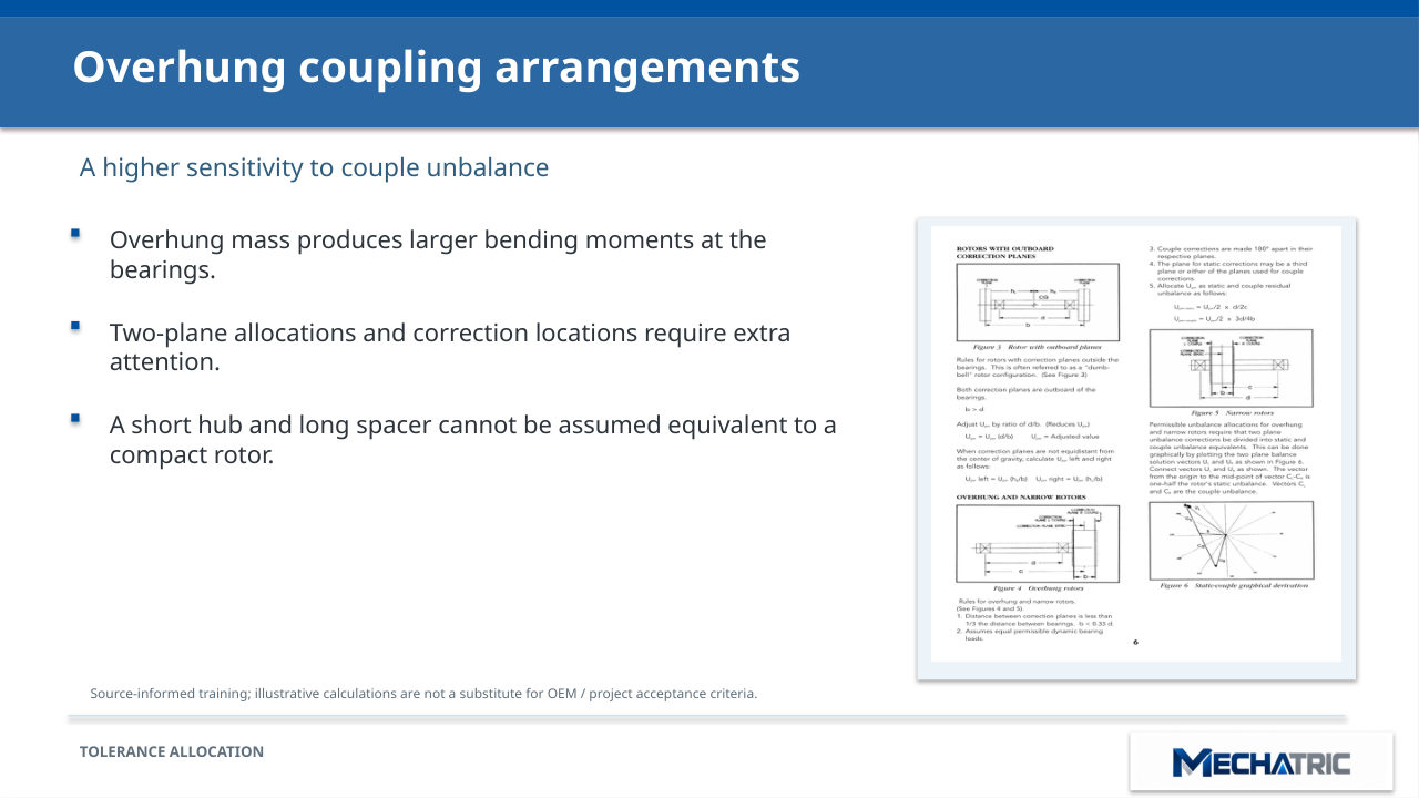
Overhung coupling arrangements
- A higher sensitivity to couple unbalance
- Overhung mass produces larger bending moments at the bearings.
- Two-plane allocations and correction locations require extra attention.
- A short hub and long spacer cannot be assumed equivalent to a compact rotor.
- Source-informed training; illustrative calculations are not a substitute for OEM / project acceptance criteria.
Balancing Engineering
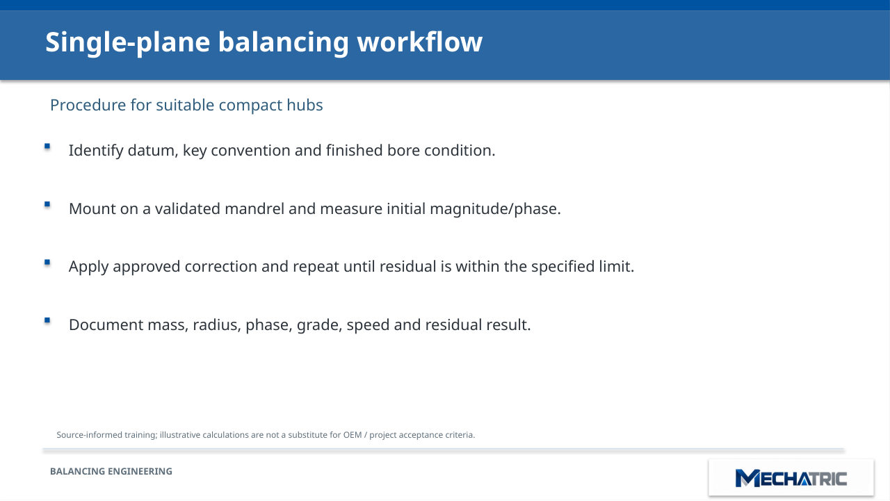
Single-plane balancing workflow
- Procedure for suitable compact hubs
- Identify datum, key convention and finished bore condition.
- Mount on a validated mandrel and measure initial magnitude/phase.
- Apply approved correction and repeat until residual is within the specified limit.
- Document mass, radius, phase, grade, speed and residual result.
- Source-informed training; illustrative calculations are not a substitute for OEM / project acceptance criteria.
Two-plane balancing workflow
- Procedure for rigid coupling subassemblies
- Identify plane A and plane B and record axial separation.
- Perform calibrated measurement or influence-coefficient trial corrections.
- Calculate vector corrections independently for both planes.
- Re-run and verify each plane against its allocated tolerance.
- Source-informed training; illustrative calculations are not a substitute for OEM / project acceptance criteria.
Balancing-machine setup
- Repeatability is essential
- Check machine calibration, drive method, tooling and mandrel concentricity.
- Minimize mounting errors, runout and contamination.
- Ensure speed and sensitivity suit the component and tolerance.
- Perform repeat runs and reversal/remount checks where appropriate.
- Source-informed training; illustrative calculations are not a substitute for OEM / project acceptance criteria.
Residual unbalance verification
- Acceptance must be measurable
- State permitted residual unbalance and plane basis.
- Measure residual vectors after the final correction.
- Consider uncertainty, tooling effects and machine error; ISO 1940-2 addresses balance errors.
- Record evidence, not only a pass/fail statement.
- Source-informed training; illustrative calculations are not a substitute for OEM / project acceptance criteria.
Keyway Control
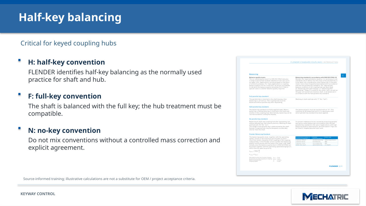
Half-key balancing
- Critical for keyed coupling hubs
- H: half-key convention
- FLENDER identifies half-key balancing as the normally used practice for shaft and hub.
- F: full-key convention
- The shaft is balanced with the full key; the hub treatment must be compatible.
- N: no-key convention
- Do not mix conventions without a controlled mass correction and explicit agreement.
Balancing Engineering
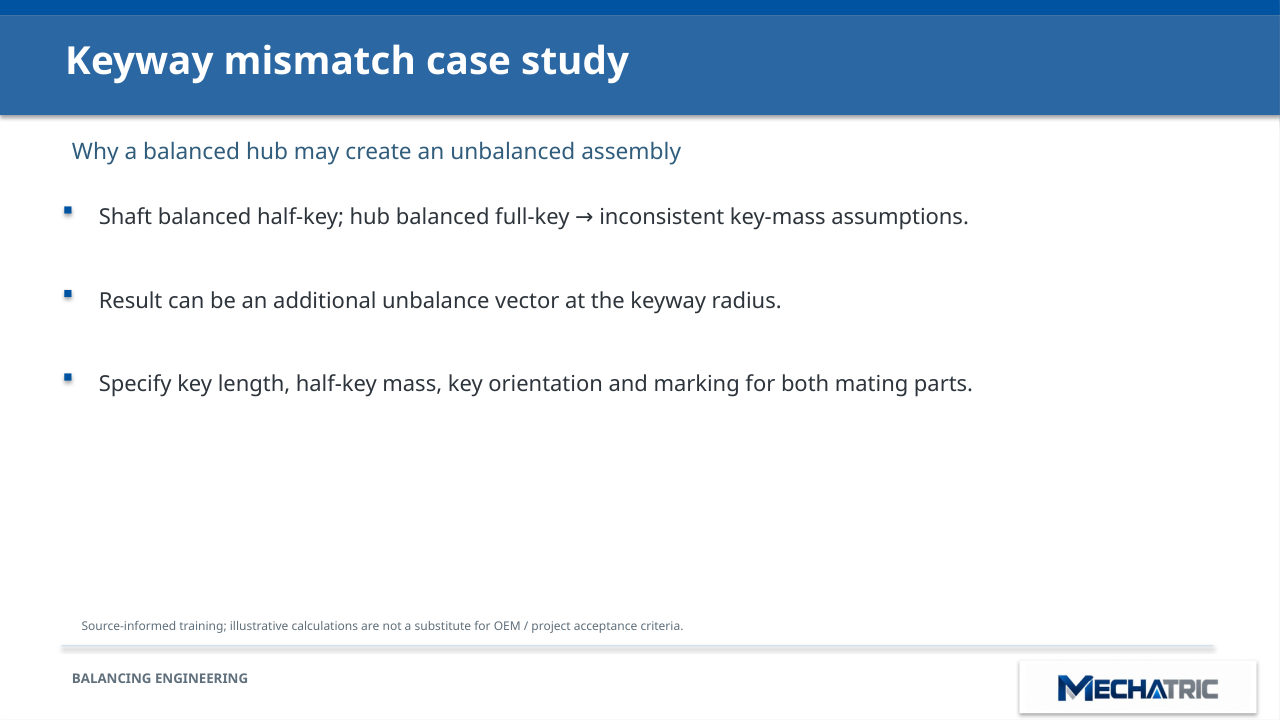
Keyway mismatch case study
- Why a balanced hub may create an unbalanced assembly
- Shaft balanced half-key; hub balanced full-key inconsistent key-mass assumptions.
- →
- Result can be an additional unbalance vector at the keyway radius.
- Specify key length, half-key mass, key orientation and marking for both mating parts.
- Source-informed training; illustrative calculations are not a substitute for OEM / project acceptance criteria.
Manufacturer-Specific
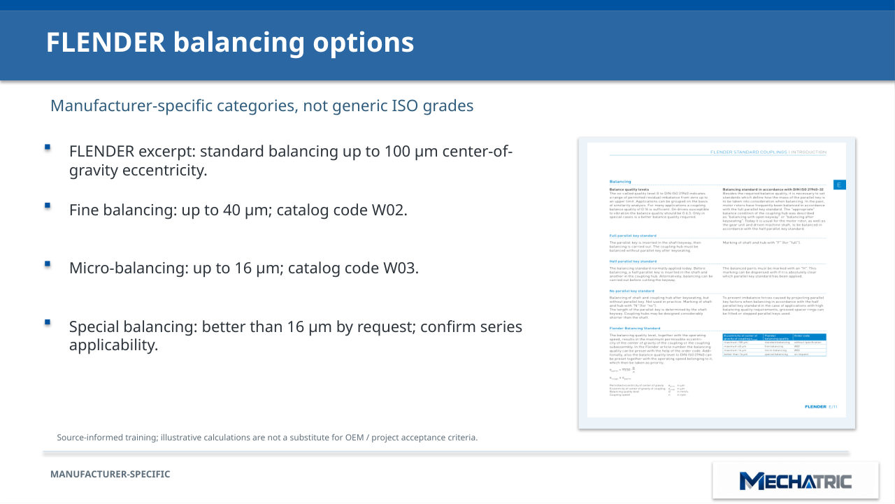
FLENDER balancing options
- Manufacturer-specific categories, not generic ISO grades
- FLENDER excerpt: standard balancing up to 100 µm center-of- gravity eccentricity.
- Fine balancing: up to 40 µm; catalog code W02.
- Micro-balancing: up to 16 µm; catalog code W03.
- Special balancing: better than 16 µm by request; confirm series applicability.
- Source-informed training; illustrative calculations are not a substitute for OEM / project acceptance criteria.
Balancing Engineering
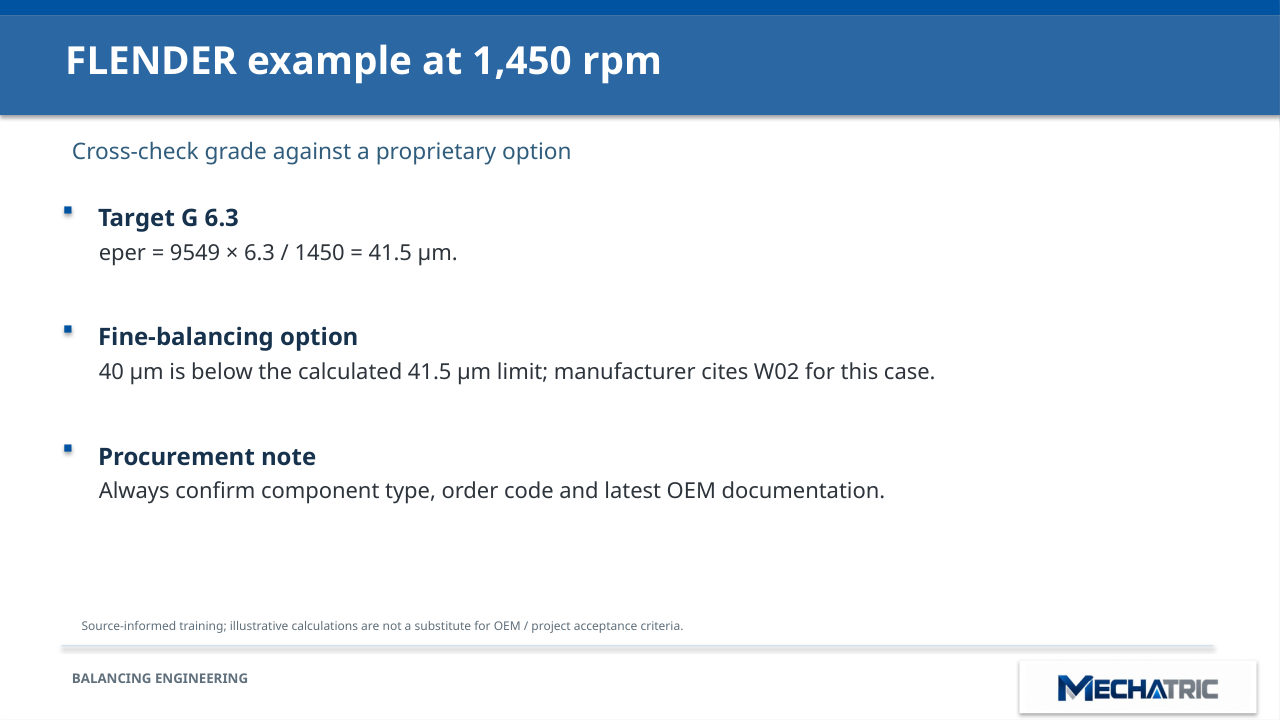
FLENDER example at 1,450 rpm
- Cross-check grade against a proprietary option
- Target G 6.3 eper = 9549 × 6.3 / 1450 = 41.5 µm.
- Fine-balancing option
- 40 µm is below the calculated 41.5 µm limit; manufacturer cites W02 for this case.
- Procurement note
- Always confirm component type, order code and latest OEM documentation.
- Source-informed training; illustrative calculations are not a substitute for OEM / project acceptance criteria.
Coupling Families
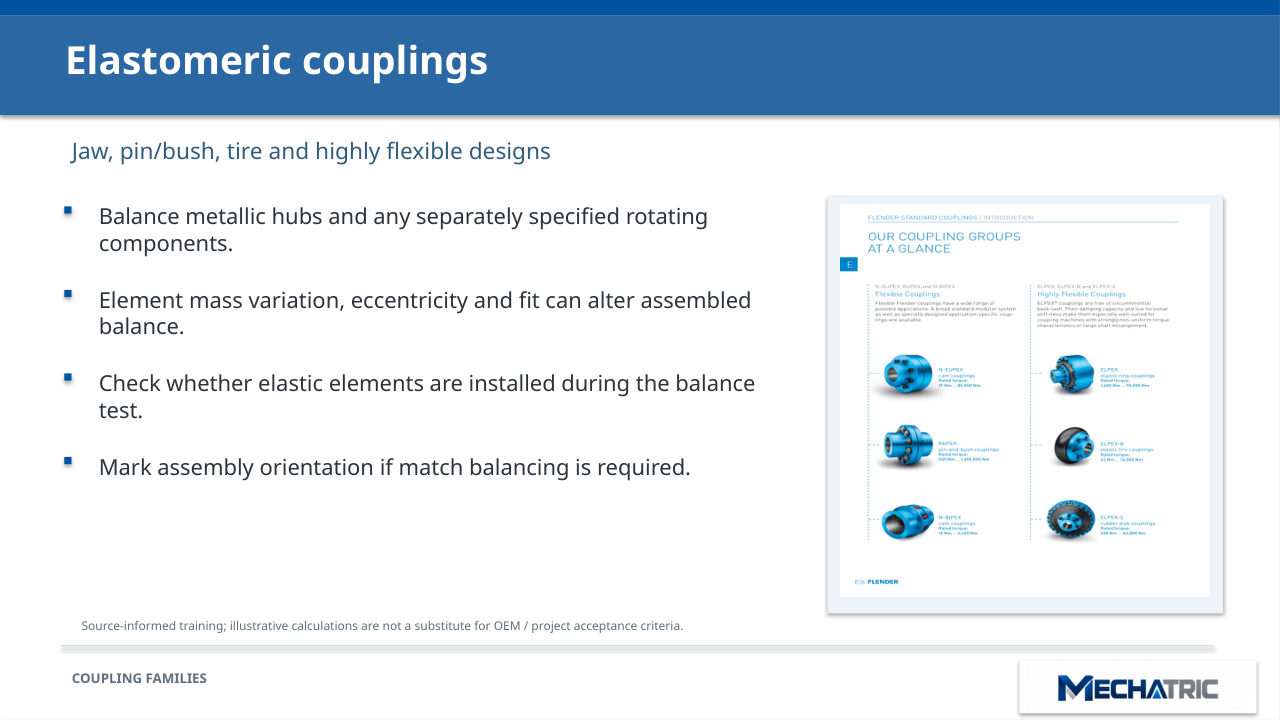
Elastomeric couplings
- Jaw, pin/bush, tire and highly flexible designs
- Balance metallic hubs and any separately specified rotating components.
- Element mass variation, eccentricity and fit can alter assembled balance.
- Check whether elastic elements are installed during the balance test.
- Mark assembly orientation if match balancing is required.
- Source-informed training; illustrative calculations are not a substitute for OEM / project acceptance criteria.
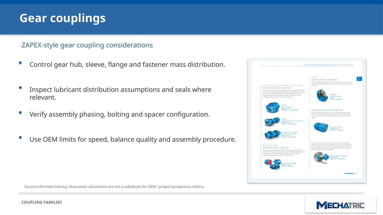
Gear couplings
- ZAPEX-style gear coupling considerations
- Control gear hub, sleeve, flange and fastener mass distribution.
- Inspect lubricant distribution assumptions and seals where relevant.
- Verify assembly phasing, bolting and spacer configuration.
- Use OEM limits for speed, balance quality and assembly procedure.
- Source-informed training; illustrative calculations are not a substitute for OEM / project acceptance criteria.
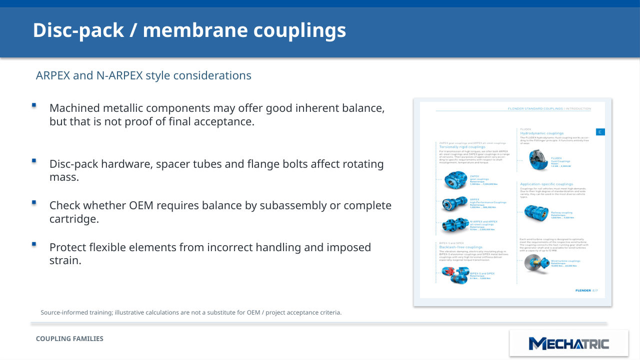
Disc-pack / membrane couplings
- ARPEX and N-ARPEX style considerations
- Machined metallic components may offer good inherent balance, but that is not proof of final acceptance.
- Disc-pack hardware, spacer tubes and flange bolts affect rotating mass.
- Check whether OEM requires balance by subassembly or complete cartridge.
- Protect flexible elements from incorrect handling and imposed strain.
- Source-informed training; illustrative calculations are not a substitute for OEM / project acceptance criteria.
Balancing Engineering
Spacer couplings
- Long DBSE and high-speed applications
- A long spacer raises sensitivity to eccentricity, assembly runout and potential flexible-rotor behavior.
- Evaluate critical speed and rotor dynamics when warranted.
- Record spacer orientation, fit, flange pilots and fastener grades.
- Specify complete-assembly balancing when required by the project or OEM.
- Source-informed training; illustrative calculations are not a substitute for OEM / project acceptance criteria.
Coupling Families
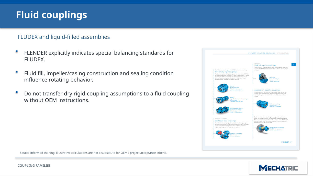
Fluid couplings
- FLUDEX and liquid-filled assemblies
- FLENDER explicitly indicates special balancing standards for FLUDEX.
- Fluid fill, impeller/casing construction and sealing condition influence rotating behavior.
- Do not transfer dry rigid-coupling assumptions to a fluid coupling without OEM instructions.
- Source-informed training; illustrative calculations are not a substitute for OEM / project acceptance criteria.
Balancing Engineering
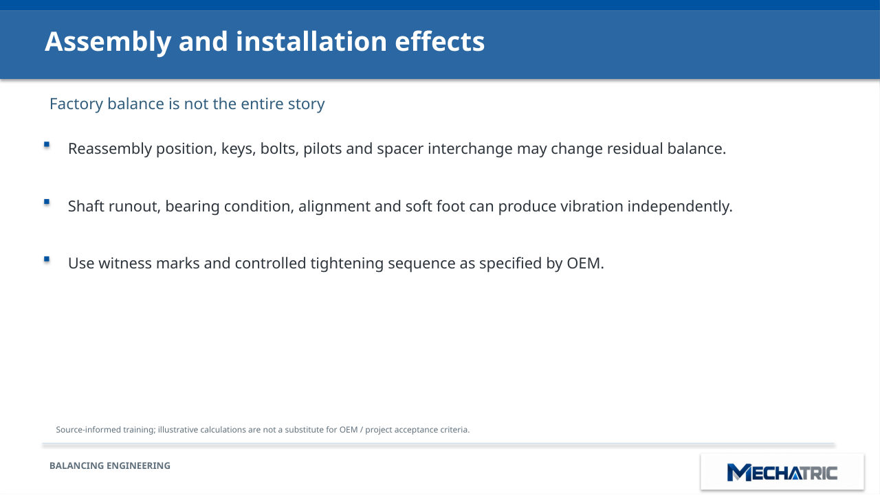
Assembly and installation effects
- Factory balance is not the entire story
- Reassembly position, keys, bolts, pilots and spacer interchange may change residual balance.
- Shaft runout, bearing condition, alignment and soft foot can produce vibration independently.
- Use witness marks and controlled tightening sequence as specified by OEM.
- Source-informed training; illustrative calculations are not a substitute for OEM / project acceptance criteria.
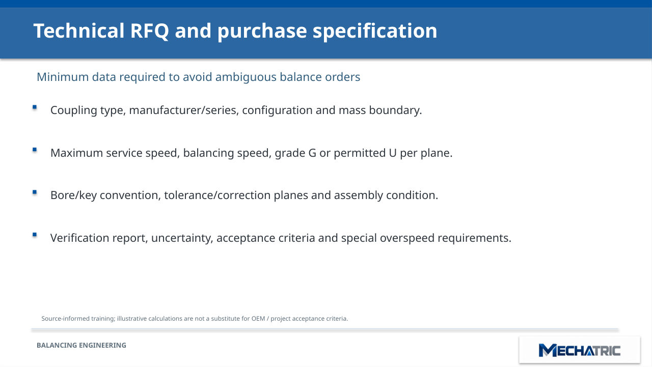
Technical RFQ and purchase specification
- Minimum data required to avoid ambiguous balance orders
- Coupling type, manufacturer/series, configuration and mass boundary.
- Maximum service speed, balancing speed, grade G or permitted U per plane.
- Bore/key convention, tolerance/correction planes and assembly condition.
- Verification report, uncertainty, acceptance criteria and special overspeed requirements.
- Source-informed training; illustrative calculations are not a substitute for OEM / project acceptance criteria.
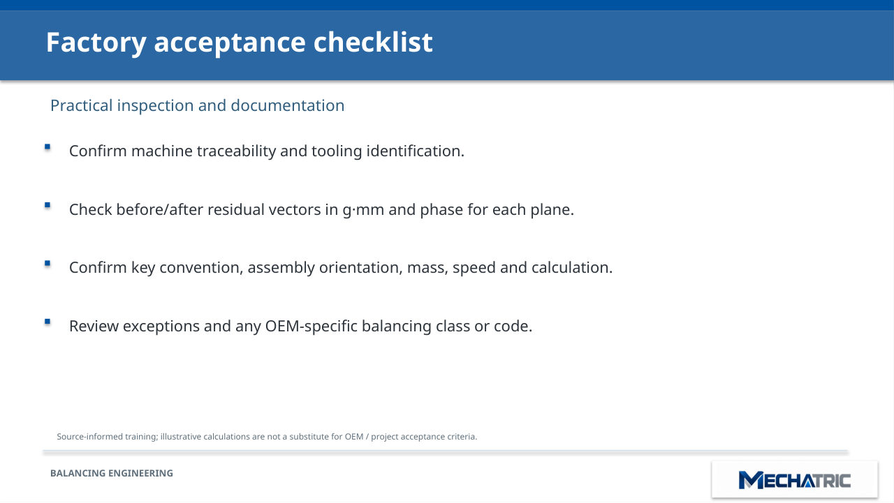
Factory acceptance checklist
- Practical inspection and documentation
- Confirm machine traceability and tooling identification.
- Check before/after residual vectors in g·mm and phase for each plane.
- Confirm key convention, assembly orientation, mass, speed and calculation.
- Review exceptions and any OEM-specific balancing class or code.
- Source-informed training; illustrative calculations are not a substitute for OEM / project acceptance criteria.
References & Close
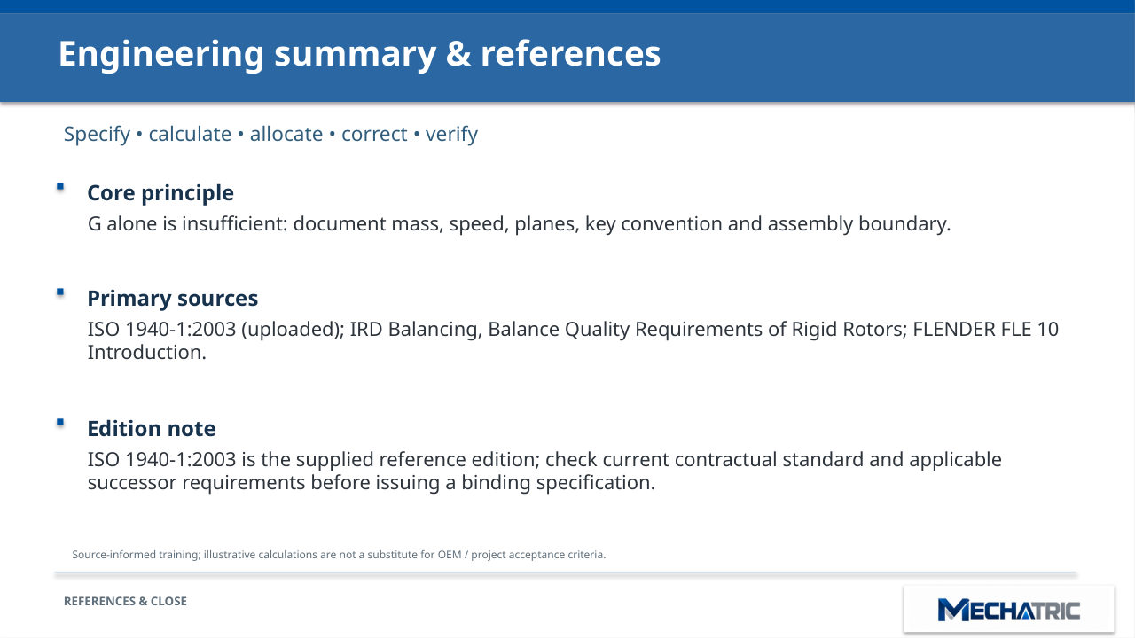
Engineering summary & references
- Specify • calculate • allocate • correct • verify
- Core principle
- G alone is insufficient: document mass, speed, planes, key convention and assembly boundary.
- Primary sources
- ISO 1940-1:2003 (uploaded); IRD Balancing, Balance Quality Requirements of Rigid Rotors; FLENDER FLE 10
- Introduction.
- Edition note
Need engineering support?
Send your application data and the existing equipment details – MECHATRIC reviews the selection, specification or replacement and prepares the RFQ.
Training material prepared by MECHATRIC from the cited standards and manufacturer documentation. Trademarks belong to their respective owners. Confirm all requirements and ratings against the current editions and manufacturer data for each project.