
MECHATRIC Coupling Academy
API 610 Pump Coupling Specification – Masterclass
Ten-point specification framework for API-compliant centrifugal-pump couplings (API 610 / ISO 13709, Clause 7.2): standards hierarchy, construction, DBSE, rating, balance, fits and keys, guards and the RFQ compliance matrix.

Swipe or use the arrows
Presentation Outline
Key points of each slide – a quick engineering reference.
02 – NORMATIVE FRAMEWORK
Standards Hierarchy & Applicability
- API 610 / ISO 13709 governs centrifugal pumps and their drive- train interfaces.
- ISO 14691 covers general-purpose flexible couplings; ISO 10441 / API 671 covers special-purpose couplings.
- API 610 §7.2.4 requires these additional standards when specified.
- The purchaser must state the applicable edition, deviations and project-specific requirements.
- Key Distinction: API 610 pump compliance does not automatically certify a coupling to API 671.
03 – CONSTRUCTION
Default Coupling Configuration
- Default: all-metal flexible-element, spacer-type coupling, unless otherwise specified.
- Manufacture per AGMA 9000 Class 9; flexible elements of corrosion-resistant material.
- Positive spacer retention after flexible-element rupture; bolt heads alone may be inadequate.
- Steel hubs; alignability without dismantling the spacer.
- Specify: Type, element alloy, spacer retention concept, hub steel grade, alignment provisions
04 – GEOMETRY AND MAINTAINABILITY
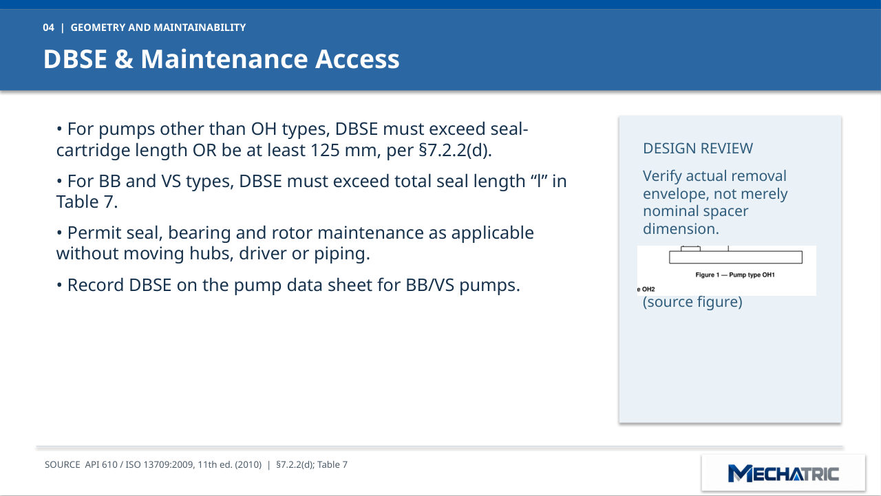
DBSE & Maintenance Access
- For pumps other than OH types, DBSE must exceed seal- cartridge length OR be at least 125 mm, per §7.2.2(d).
- For BB and VS types, DBSE must exceed total seal length “l” in Table 7.
- Permit seal, bearing and rotor maintenance as applicable without moving hubs, driver or piping.
- Record DBSE on the pump data sheet for BB/VS pumps.
- Design Review: Verify actual removal envelope, not merely nominal spacer dimension. OH2 pump arrangement (source figure)
05 – MECHANICAL SIZING
Power, Torque & Speed Rating
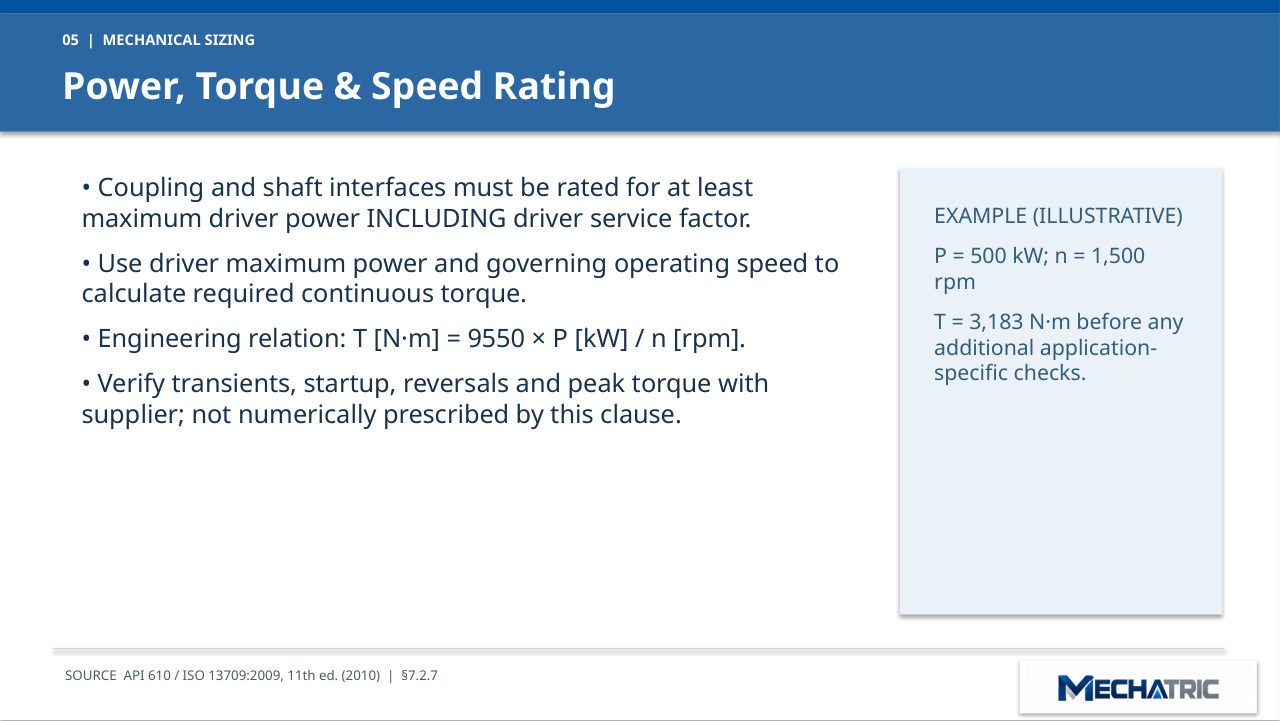
- Coupling and shaft interfaces must be rated for at least maximum driver power INCLUDING driver service factor.
- Use driver maximum power and governing operating speed to calculate required continuous torque.
- Engineering relation: T [N·m] = 9550 × P [kW] / n [rpm].
- Verify transients, startup, reversals and peak torque with supplier; not numerically prescribed by this clause. EXAMPLE (ILLUSTRATIVE) P = 500 kW; n = 1,500 rpm T = 3,183 N·m before any additional application- specific checks.
06 – ROTOR DYNAMICS
Balance & High-Speed Conditions
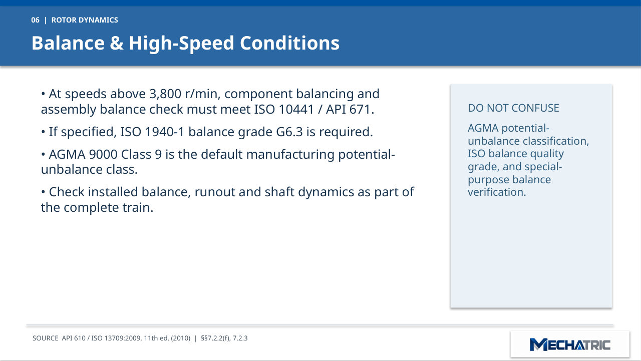
- At speeds above 3,800 r/min, component balancing and assembly balance check must meet ISO 10441 / API 671.
- If specified, ISO 1940-1 balance grade G6.3 is required.
- AGMA 9000 Class 9 is the default manufacturing potential- unbalance class.
- Check installed balance, runout and shaft dynamics as part of the complete train.
- Do Not Confuse: AGMA potential- unbalance classification, ISO balance quality grade, and special- purpose balance verification.
07 – FITS, KEYS AND REMOVAL
Shaft–Hub Interface Requirements
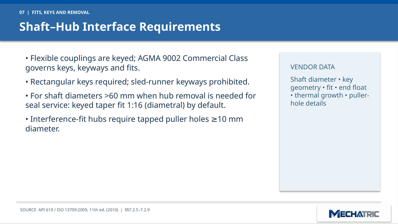
- Flexible couplings are keyed; AGMA 9002 Commercial Class governs keys, keyways and fits.
- Rectangular keys required; sled-runner keyways prohibited.
- For shaft diameters >60 mm when hub removal is needed for seal service: keyed taper fit 1:16 (diametral) by default.
- Interference-fit hubs require tapped puller holes 10 mm ≥ diameter.
- Vendor Data: Shaft diameter, key geometry, fit, end float, thermal growth, puller- hole details
08 – PURCHASER-SELECTED OPTIONS
Optional Hub-Mounting Arrangements
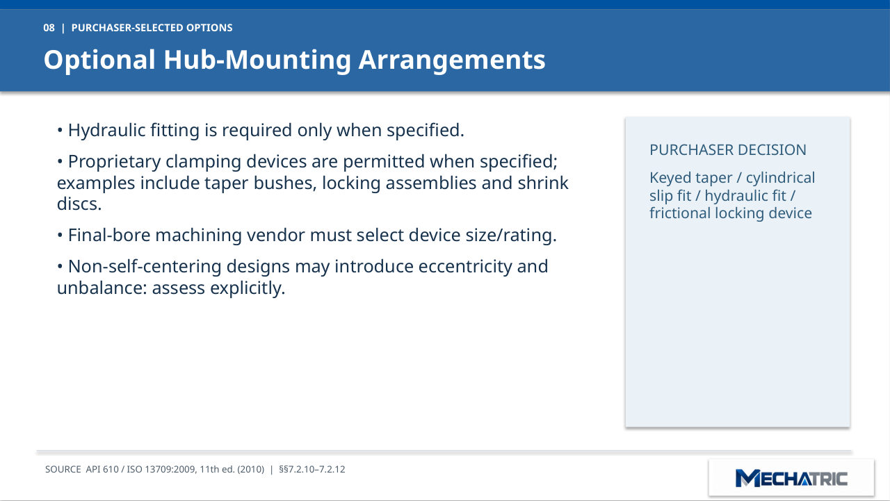
- Hydraulic fitting is required only when specified.
- Proprietary clamping devices are permitted when specified; examples include taper bushes, locking assemblies and shrink discs.
- Final-bore machining vendor must select device size/rating.
- Non-self-centering designs may introduce eccentricity and unbalance: assess explicitly.
- Purchaser Decision: Keyed taper / cylindrical slip fit / hydraulic fit / frictional locking device
09 – PROTECTIVE DESIGN
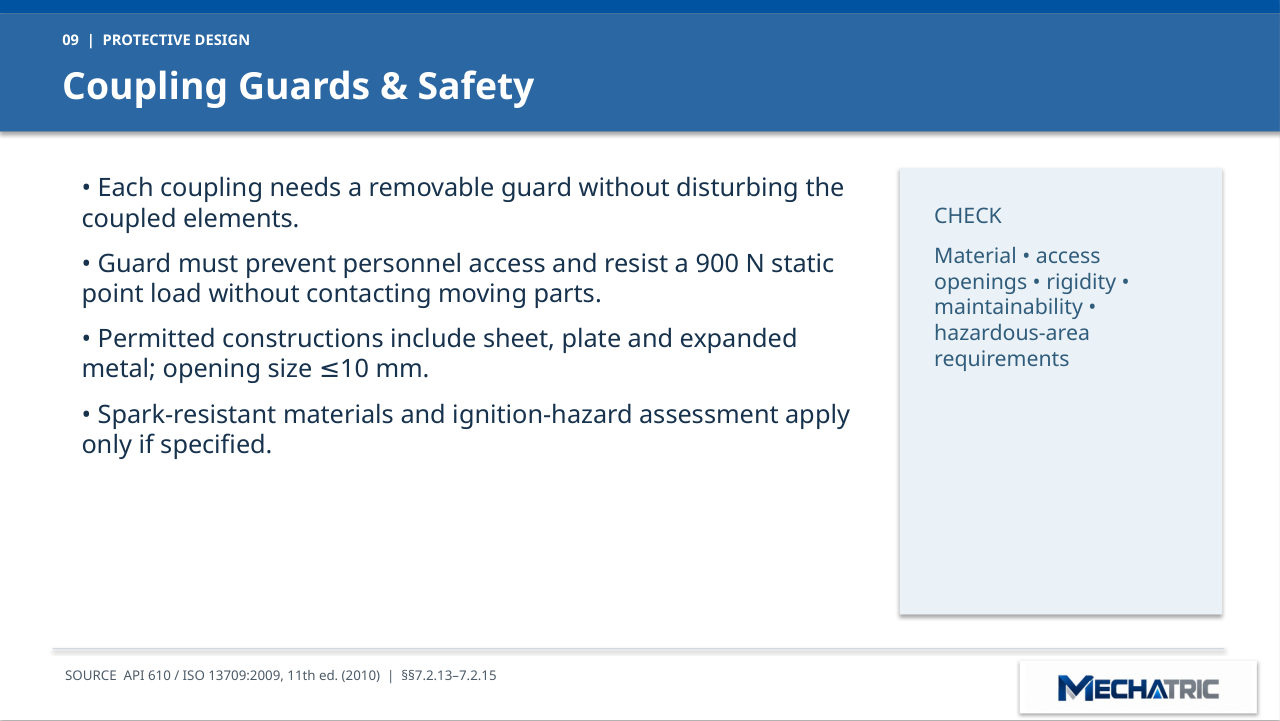
Coupling Guards & Safety
- Each coupling needs a removable guard without disturbing the coupled elements.
- Guard must prevent personnel access and resist a 900 N static point load without contacting moving parts.
- Permitted constructions include sheet, plate and expanded metal; opening size 10 mm. ≤
- Spark-resistant materials and ignition-hazard assessment apply only if specified.
- Check: Material, access openings, rigidity, maintainability, hazardous-area requirements
10 – PROCUREMENT CHECKLIST
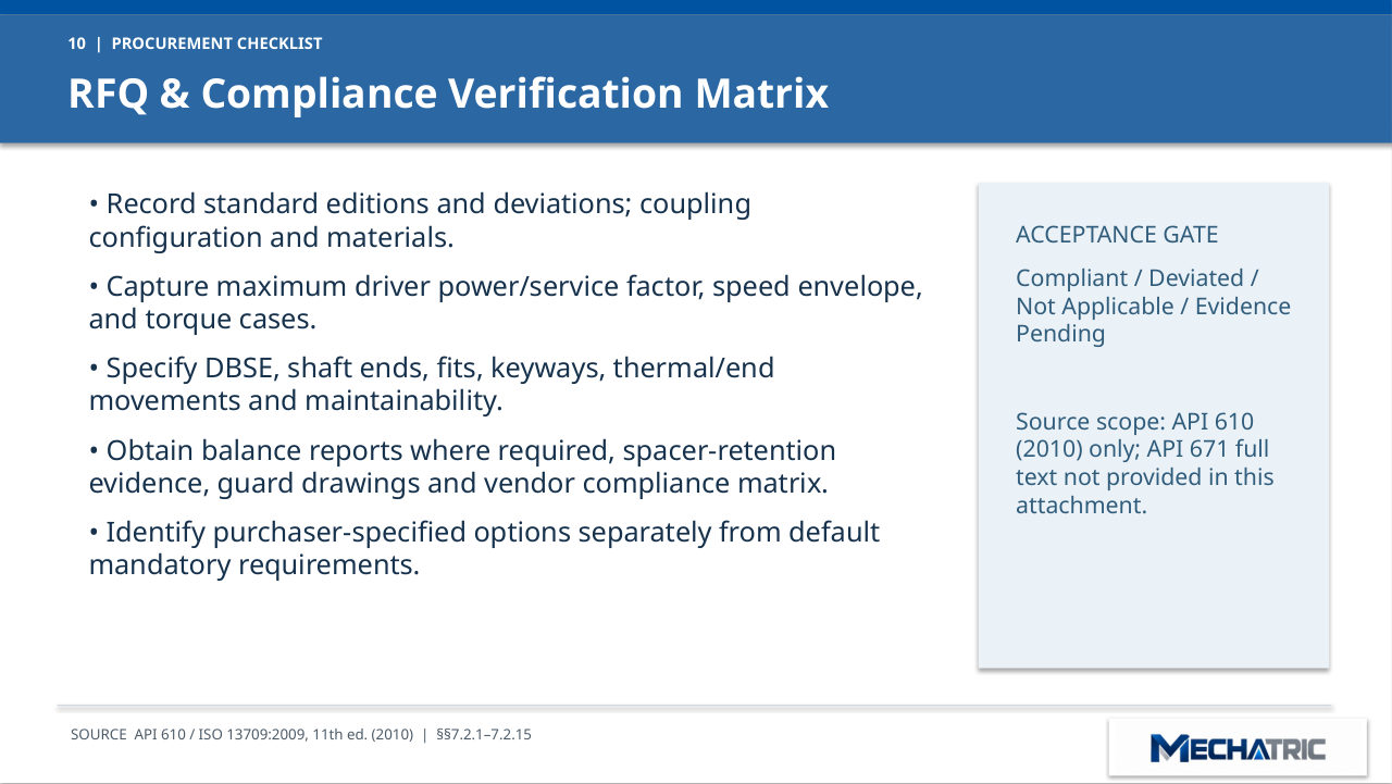
RFQ & Compliance Verification Matrix
- Record standard editions and deviations; coupling configuration and materials.
- Capture maximum driver power/service factor, speed envelope, and torque cases.
- Specify DBSE, shaft ends, fits, keyways, thermal/end movements and maintainability.
- Obtain balance reports where required, spacer-retention evidence, guard drawings and vendor compliance matrix.
- Identify purchaser-specified options separately from default mandatory requirements.
- Acceptance Gate: Compliant / Deviated / Not Applicable / Evidence Pending Source scope: API 610 (2010) only; API 671 full text not provided in this attachment.
Need engineering support?
Send your application data and the existing equipment details – MECHATRIC reviews the selection, specification or replacement and prepares the RFQ.
Training material prepared by MECHATRIC from the cited standards and manufacturer documentation. Trademarks belong to their respective owners. Confirm all requirements and ratings against the current editions and manufacturer data for each project.