
Home / Academy / Coupling Academy / FLENDER Couplings – Technical Introduction & Engineering Selection
MECHATRIC Coupling Academy
FLENDER Couplings – Technical Introduction & Engineering Selection
Coupling functions and families, FLENDER product series (N-EUPEX, RUPEX, ELPEX, ZAPEX, ARPEX, FLUDEX), misalignment, balancing, shaft-hub connections, service factors and selection checks.

Swipe or use the arrows
Presentation Outline
Key points of each slide – a quick engineering reference.
01 – INTRODUCTION
Presentation roadmap
- Drive-train fundamentals and coupling functions
- Classification and FLENDER product portfolio
- Misalignment, balancing, shaft–hub connections
- Engineering selection, examples and verification
The mechanical drive train
- Typical architecture: motor
- coupling
- gear unit
- →
- →
- →
What does a coupling do?
- Transmit rotary motion and rated torque
- Accommodate shaft displacement while controlling
- restoring loads
- Influence torsional vibration and damping
- Provide electrical/noise isolation or torque interruption
- when designed for it
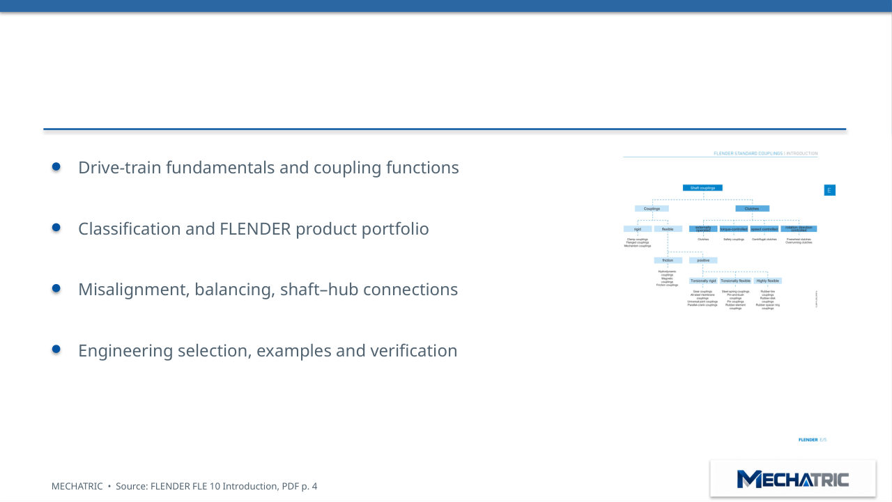
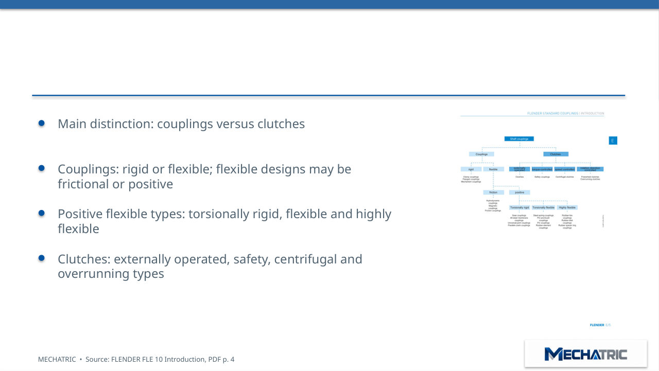
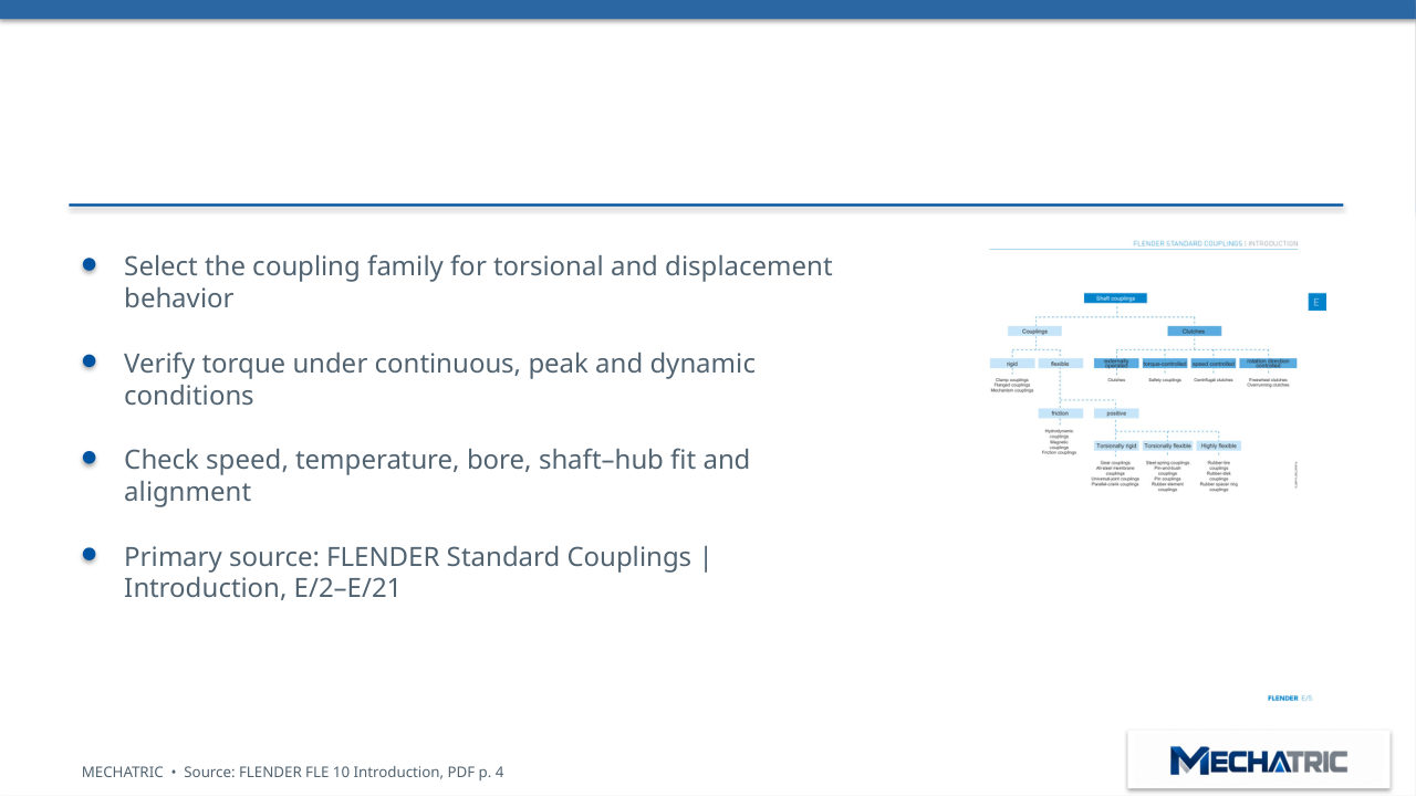
Classification of shaft couplings
- Main distinction: couplings versus clutches
- Couplings: rigid or flexible; flexible designs may be
- frictional or positive
- Positive flexible types: torsionally rigid, flexible and highly
- flexible
- Clutches: externally operated, safety, centrifugal and
02 – COUPLING FAMILIES
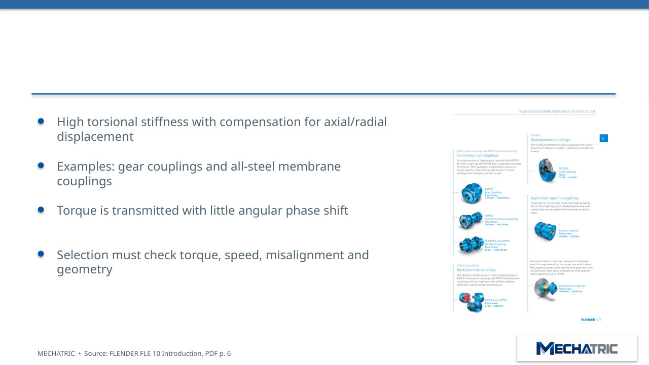
Torsionally rigid coupling principle
- High torsional stiffness with compensation for axial/radial
- displacement
- Examples: gear couplings and all-steel membrane
- couplings
- Torque is transmitted with little angular phase shift
- Selection must check torque, speed, misalignment and
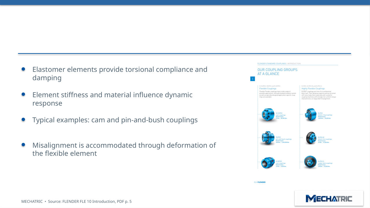
Torsionally flexible coupling principle
- Elastomer elements provide torsional compliance and
- damping
- Element stiffness and material influence dynamic
- response
- Typical examples: cam and pin-and-bush couplings
- Misalignment is accommodated through deformation of
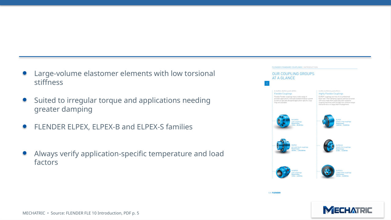
Highly flexible coupling principle
- Large-volume elastomer elements with low torsional
- stiffness
- Suited to irregular torque and applications needing
- greater damping
- FLENDER ELPEX, ELPEX-B and ELPEX-S families
- Always verify application-specific temperature and load
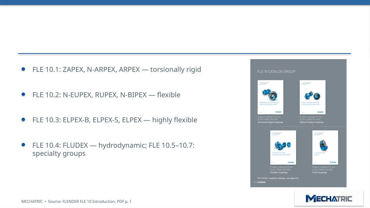
FLENDER FLE 10 catalog architecture
- FLE 10.1: ZAPEX, N-ARPEX, ARPEX — torsionally rigid
- FLE 10.2: N-EUPEX, RUPEX, N-BIPEX — flexible
- FLE 10.3: ELPEX-B, ELPEX-S, ELPEX — highly flexible
- FLE 10.4: FLUDEX — hydrodynamic; FLE 10.5–10.7:
- specialty groups
03 – PRODUCT SERIES
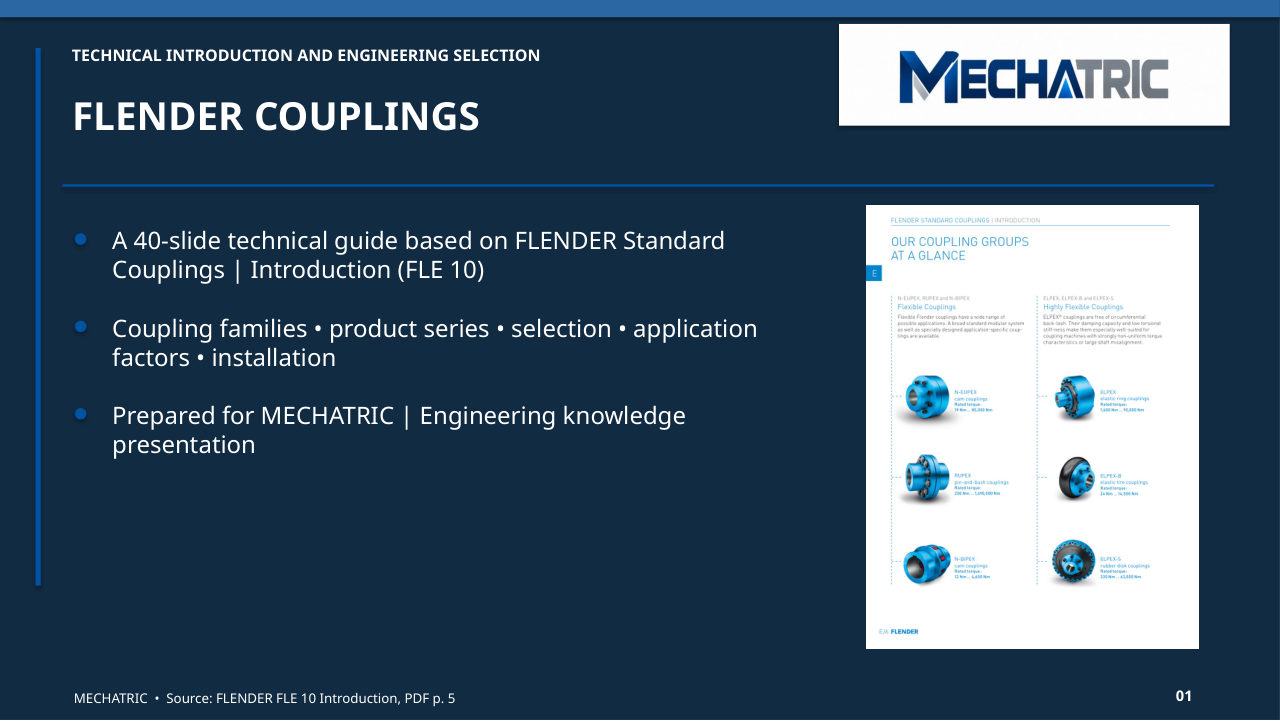
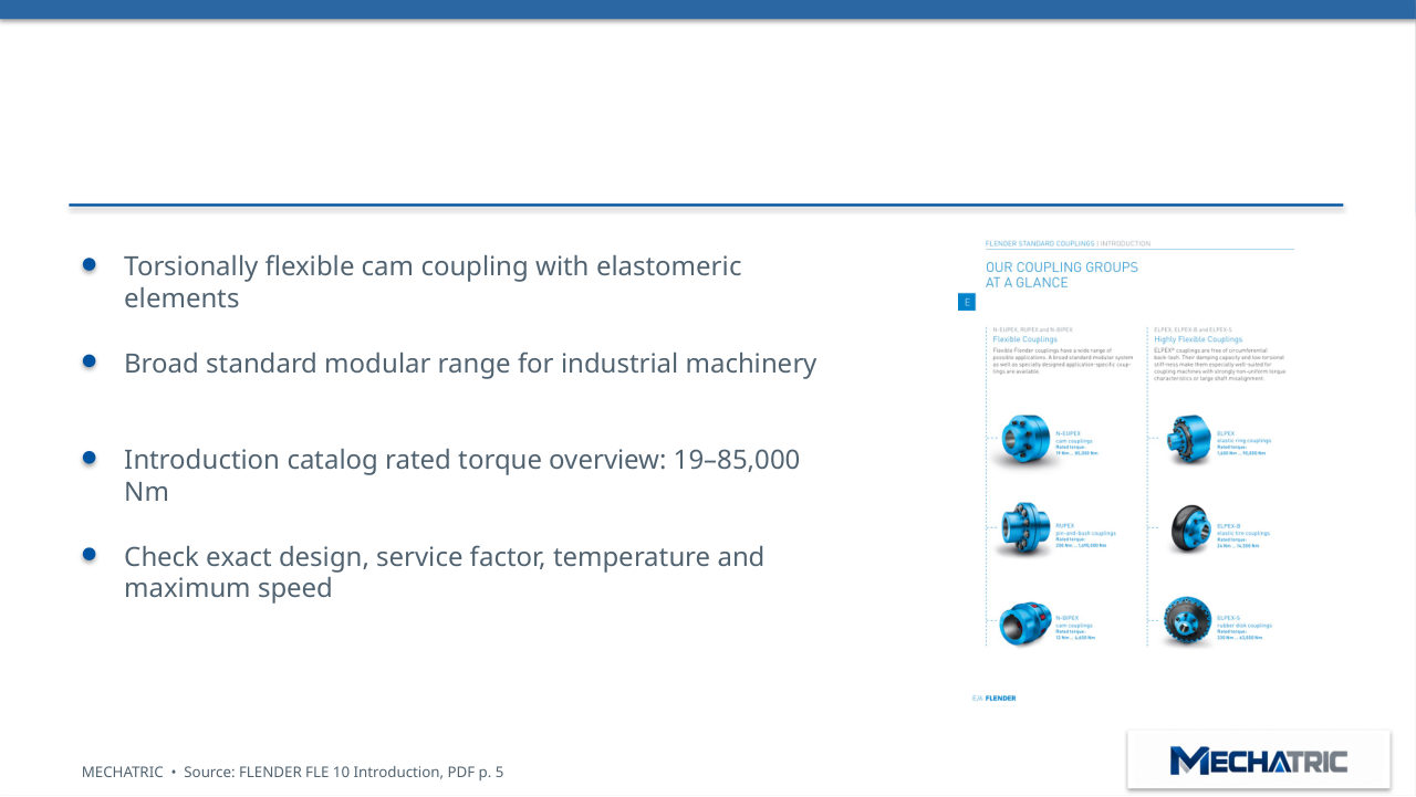
N-EUPEX | Cam coupling
- Torsionally flexible cam coupling with elastomeric
- elements
- Broad standard modular range for industrial machinery
- Introduction catalog rated torque overview: 19–85,000
- Nm
- Check exact design, service factor, temperature and
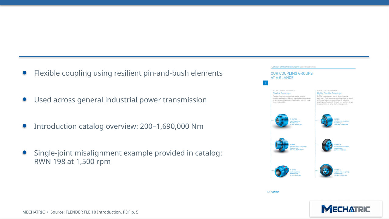
RUPEX | Pin-and-bush coupling
- Flexible coupling using resilient pin-and-bush elements
- Used across general industrial power transmission
- Introduction catalog overview: 200–1,690,000 Nm
- Single-joint misalignment example provided in catalog:
- RWN 198 at 1,500 rpm
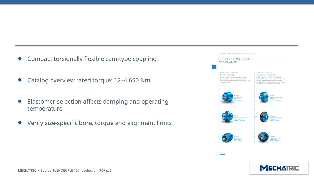
N-BIPEX | Cam coupling
- Compact torsionally flexible cam-type coupling
- Catalog overview rated torque: 12–4,650 Nm
- Elastomer selection affects damping and operating
- temperature
- Verify size-specific bore, torque and alignment limits
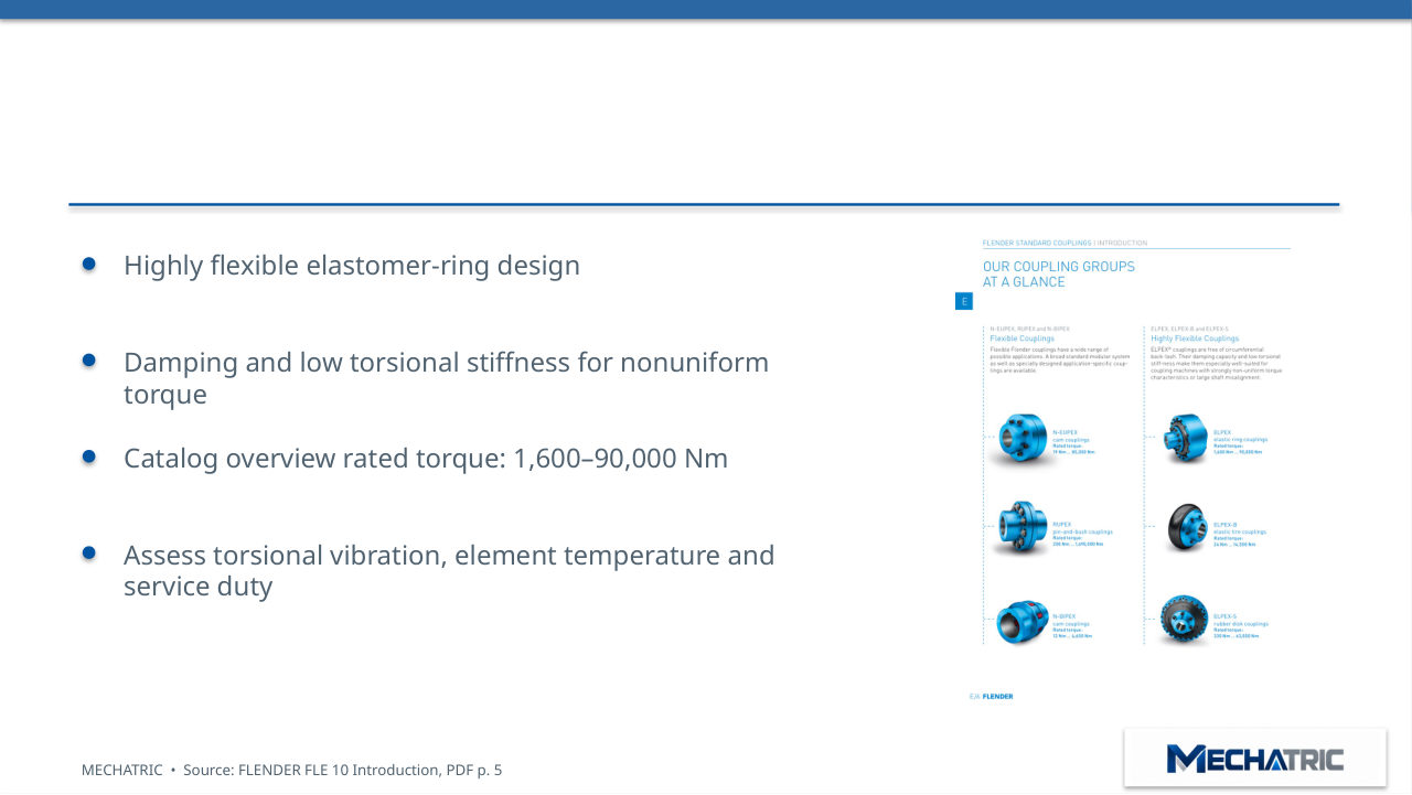
ELPEX | Elastic ring coupling
- Highly flexible elastomer-ring design
- Damping and low torsional stiffness for nonuniform
- torque
- Catalog overview rated torque: 1,600–90,000 Nm
- Assess torsional vibration, element temperature and
- service duty
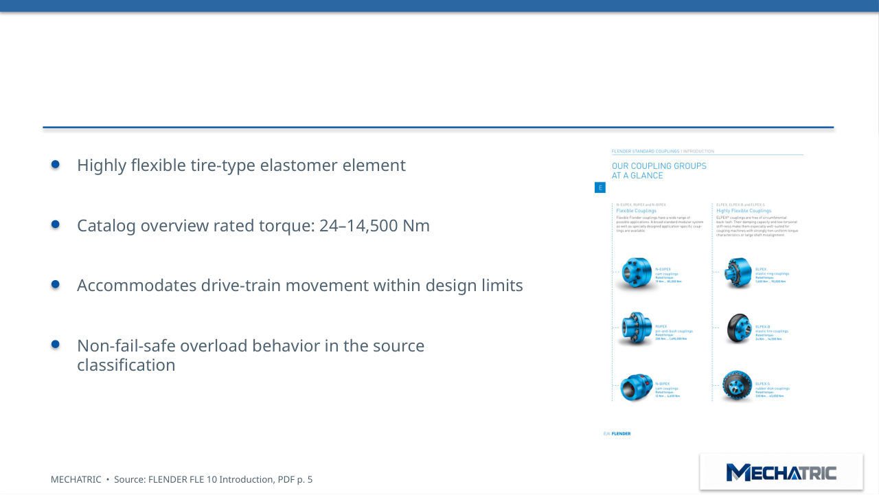
ELPEX-B | Elastic tire coupling
- Highly flexible tire-type elastomer element
- Catalog overview rated torque: 24–14,500 Nm
- Accommodates drive-train movement within design limits
- Non-fail-safe overload behavior in the source
- classification
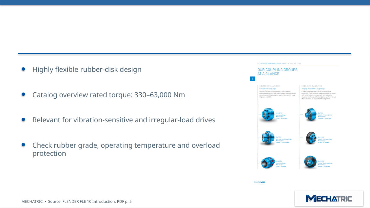
ELPEX-S | Rubber disk coupling
- Highly flexible rubber-disk design
- Catalog overview rated torque: 330–63,000 Nm
- Relevant for vibration-sensitive and irregular-load drives
- Check rubber grade, operating temperature and overload
- protection
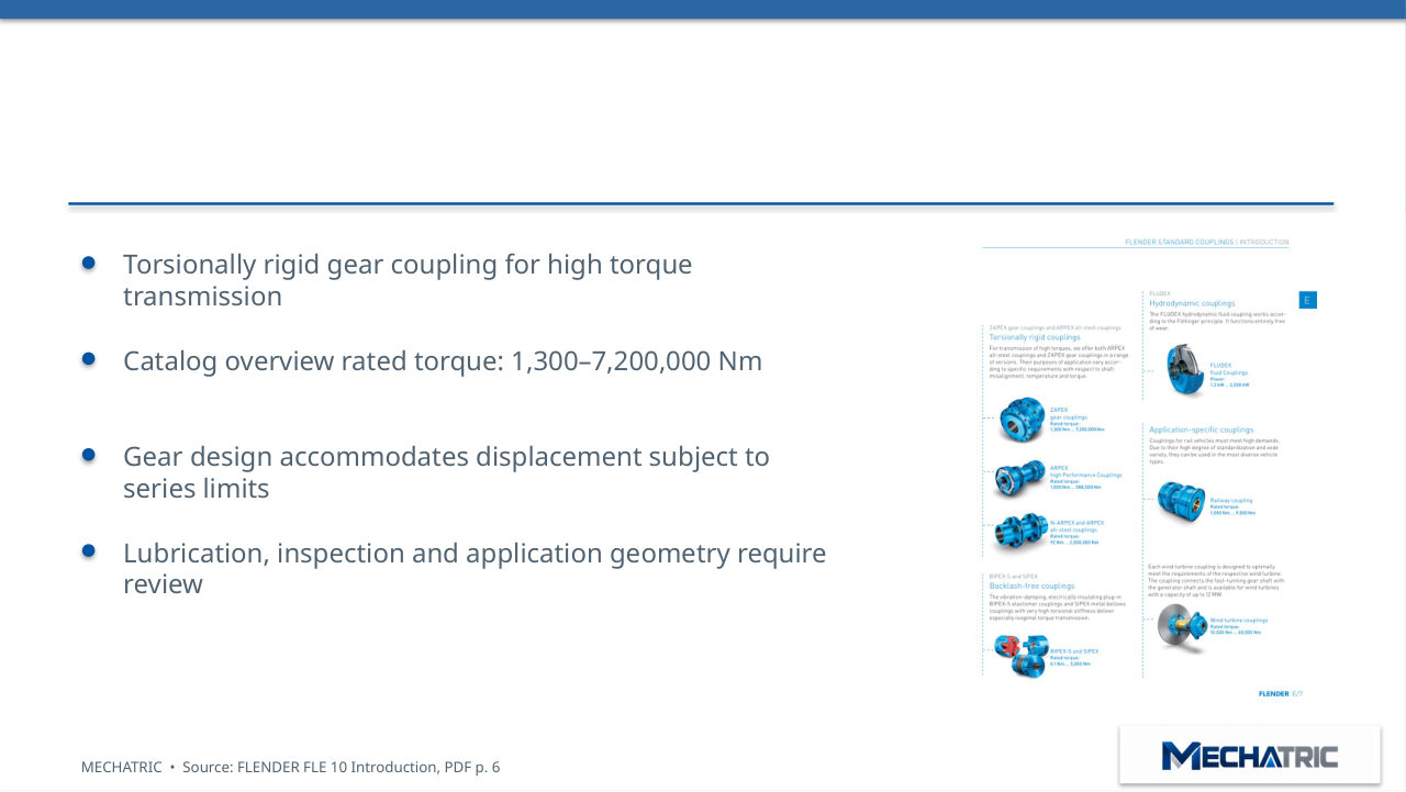
ZAPEX | Gear coupling
- Torsionally rigid gear coupling for high torque
- transmission
- Catalog overview rated torque: 1,300–7,200,000 Nm
- Gear design accommodates displacement subject to
- series limits
- Lubrication, inspection and application geometry require
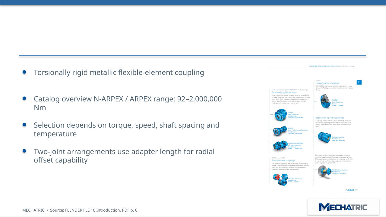
N-ARPEX | All-steel coupling
- Torsionally rigid metallic flexible-element coupling
- Catalog overview N-ARPEX / ARPEX range: 92–2,000,000
- Nm
- Selection depends on torque, speed, shaft spacing and
- temperature
- Two-joint arrangements use adapter length for radial
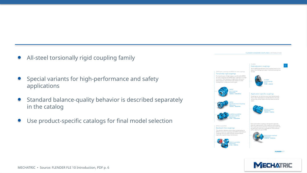
ARPEX | All-steel coupling
- All-steel torsionally rigid coupling family
- Special variants for high-performance and safety
- applications
- Standard balance-quality behavior is described separately
- in the catalog
- Use product-specific catalogs for final model selection
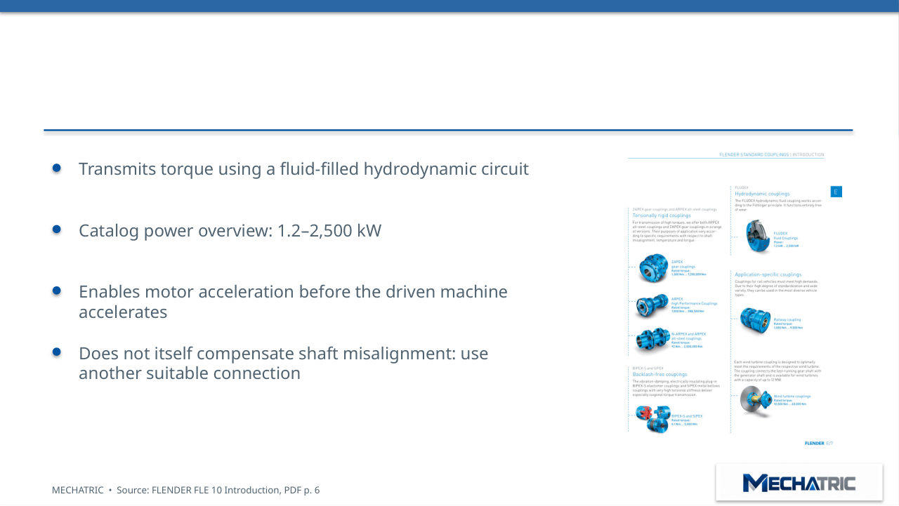
FLUDEX | Hydrodynamic coupling
- Transmits torque using a fluid-filled hydrodynamic circuit
- Catalog power overview: 1.2–2,500 kW
- Enables motor acceleration before the driven machine
- accelerates
- Does not itself compensate shaft misalignment: use
- another suitable connection
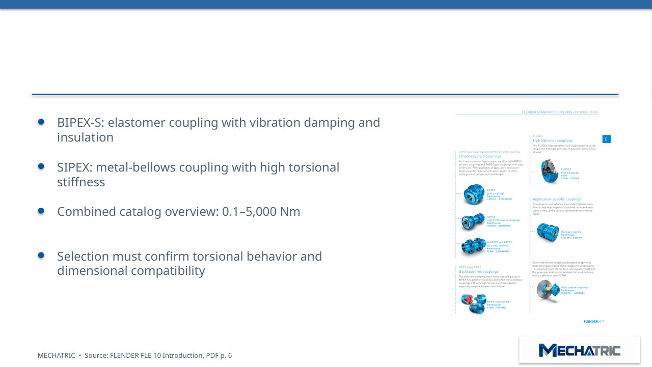
Backlash-free coupling solutions
- BIPEX-S: elastomer coupling with vibration damping and
- insulation
- SIPEX: metal-bellows coupling with high torsional
- stiffness
- Combined catalog overview: 0.1–5,000 Nm
- Selection must confirm torsional behavior and
High-performance and safety variants
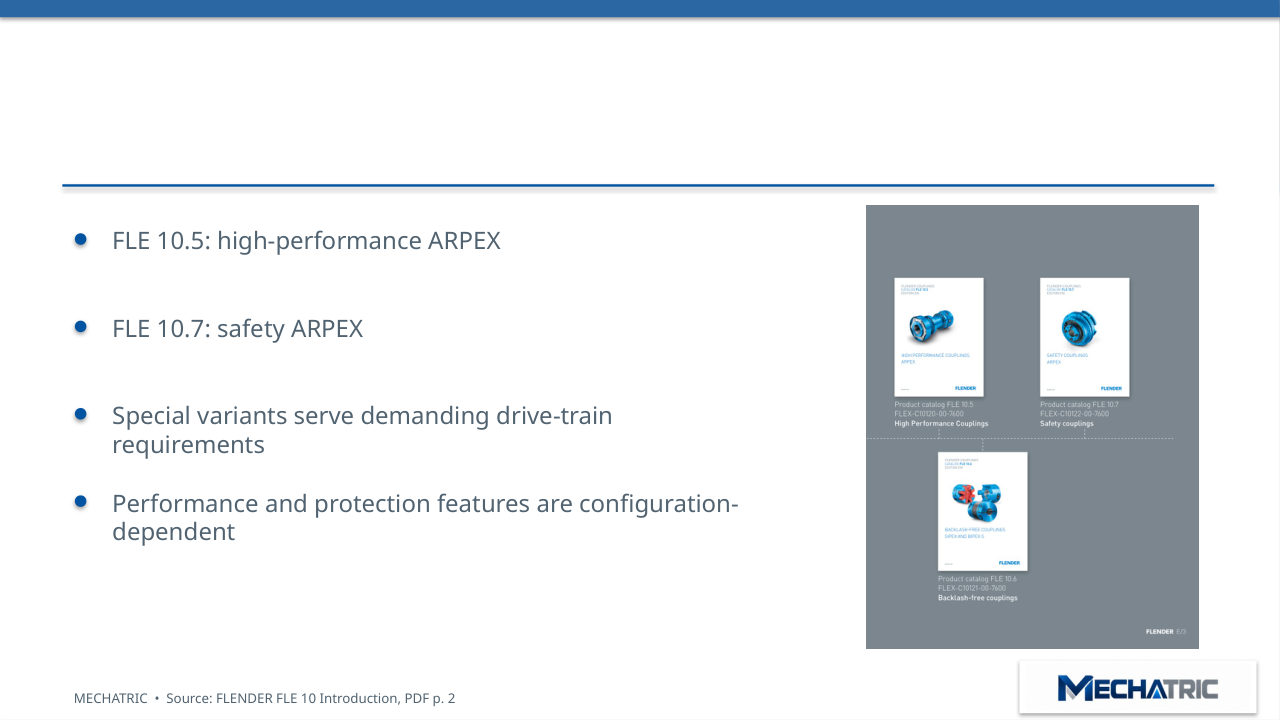
- FLE 10.5: high-performance ARPEX
- FLE 10.7: safety ARPEX
- Special variants serve demanding drive-train
- requirements
- Performance and protection features are configuration-
- dependent
Application-specific coupling designs
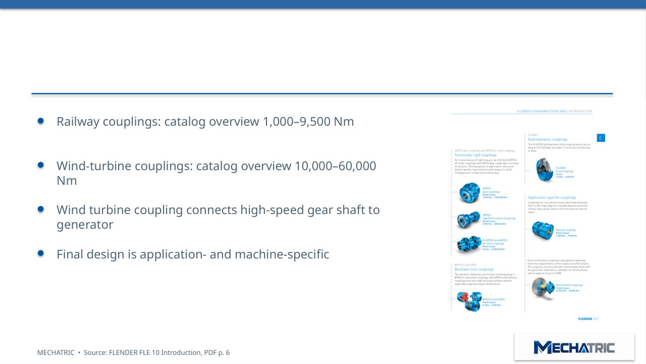
- Railway couplings: catalog overview 1,000–9,500 Nm
- Wind-turbine couplings: catalog overview 10,000–60,000
- Nm
- Wind turbine coupling connects high-speed gear shaft to
- generator
- Final design is application- and machine-specific
04 – TECHNICAL FUNDAMENTALS
Shaft misalignment | Three components
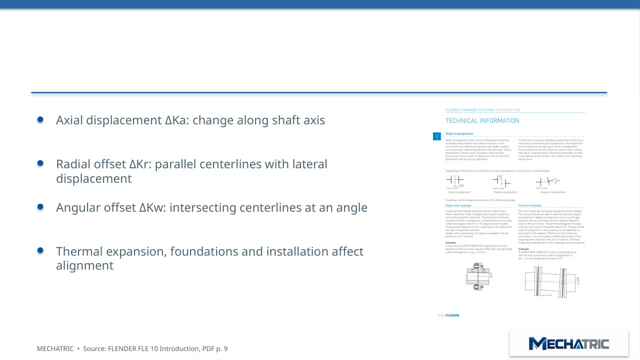
- Axial displacement ΔKa: change along shaft axis
- Radial offset ΔKr: parallel centerlines with lateral
- displacement
- Angular offset ΔKw: intersecting centerlines at an angle
- Thermal expansion, foundations and installation affect
- alignment
Single-joint vs two-joint arrangements
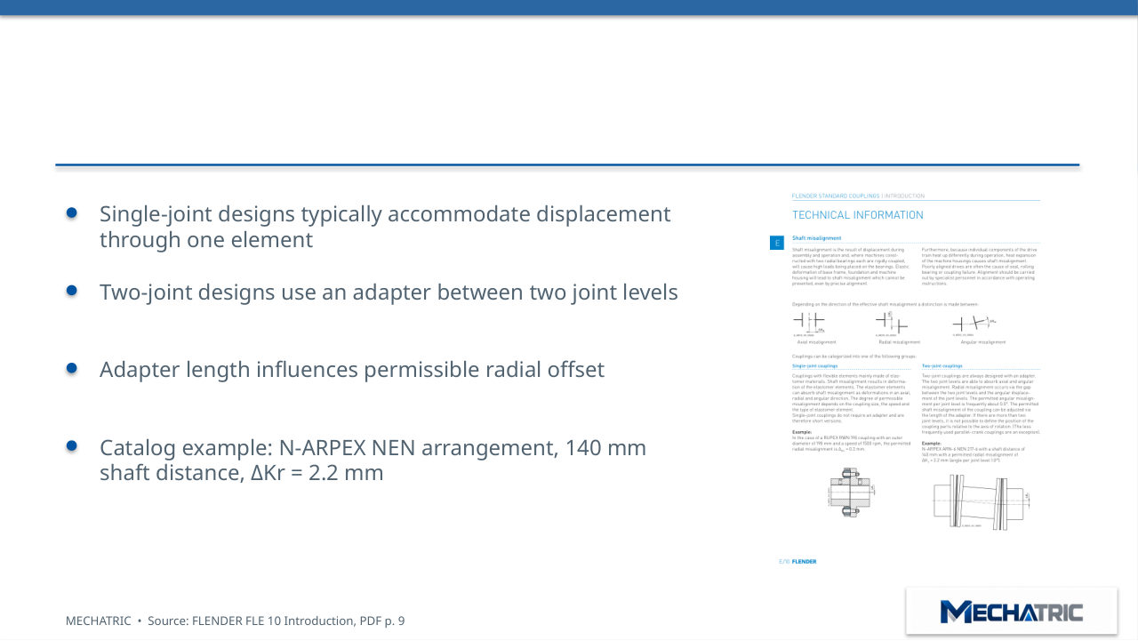
- Single-joint designs typically accommodate displacement
- through one element
- Two-joint designs use an adapter between two joint levels
- Adapter length influences permissible radial offset
- Catalog example: N-ARPEX NEN arrangement, 140 mm
- shaft distance, ΔKr = 2.2 mm
Balancing | General principles
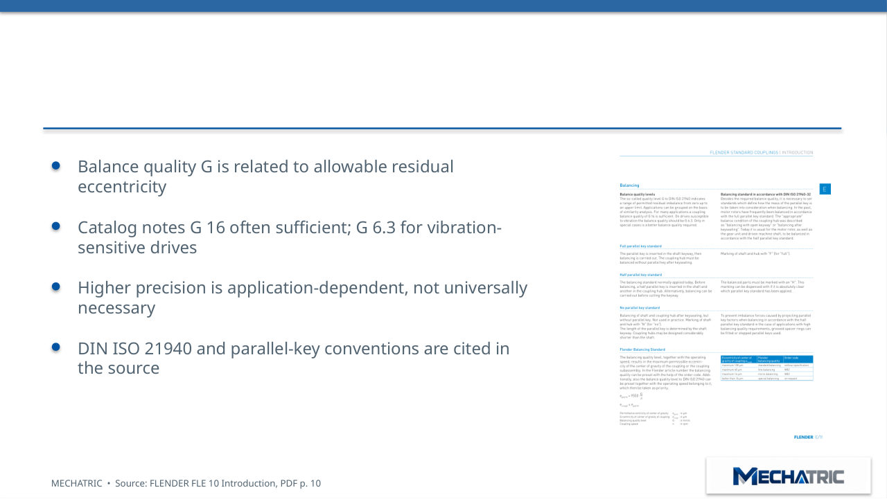
- Balance quality G is related to allowable residual
- eccentricity
- Catalog notes G 16 often sufficient; G 6.3 for vibration-
- sensitive drives
- Higher precision is application-dependent, not universally
- necessary
FLENDER balancing options
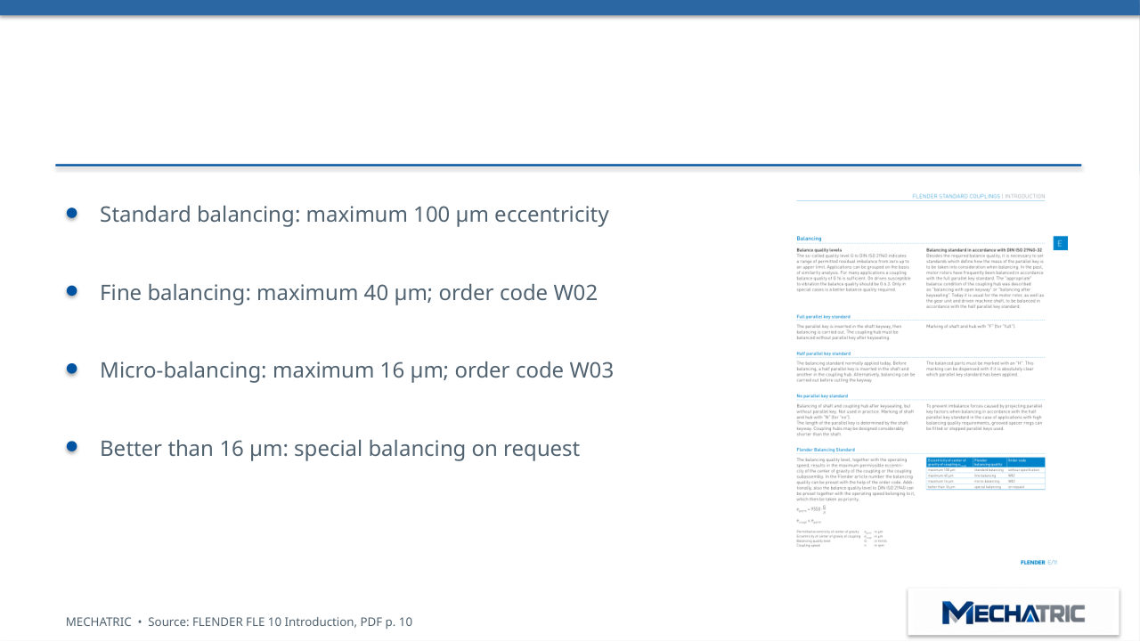
- Standard balancing: maximum 100 μm eccentricity
- Fine balancing: maximum 40 μm; order code W02
- Micro-balancing: maximum 16 μm; order code W03
- Better than 16 μm: special balancing on request
Half-key balancing convention
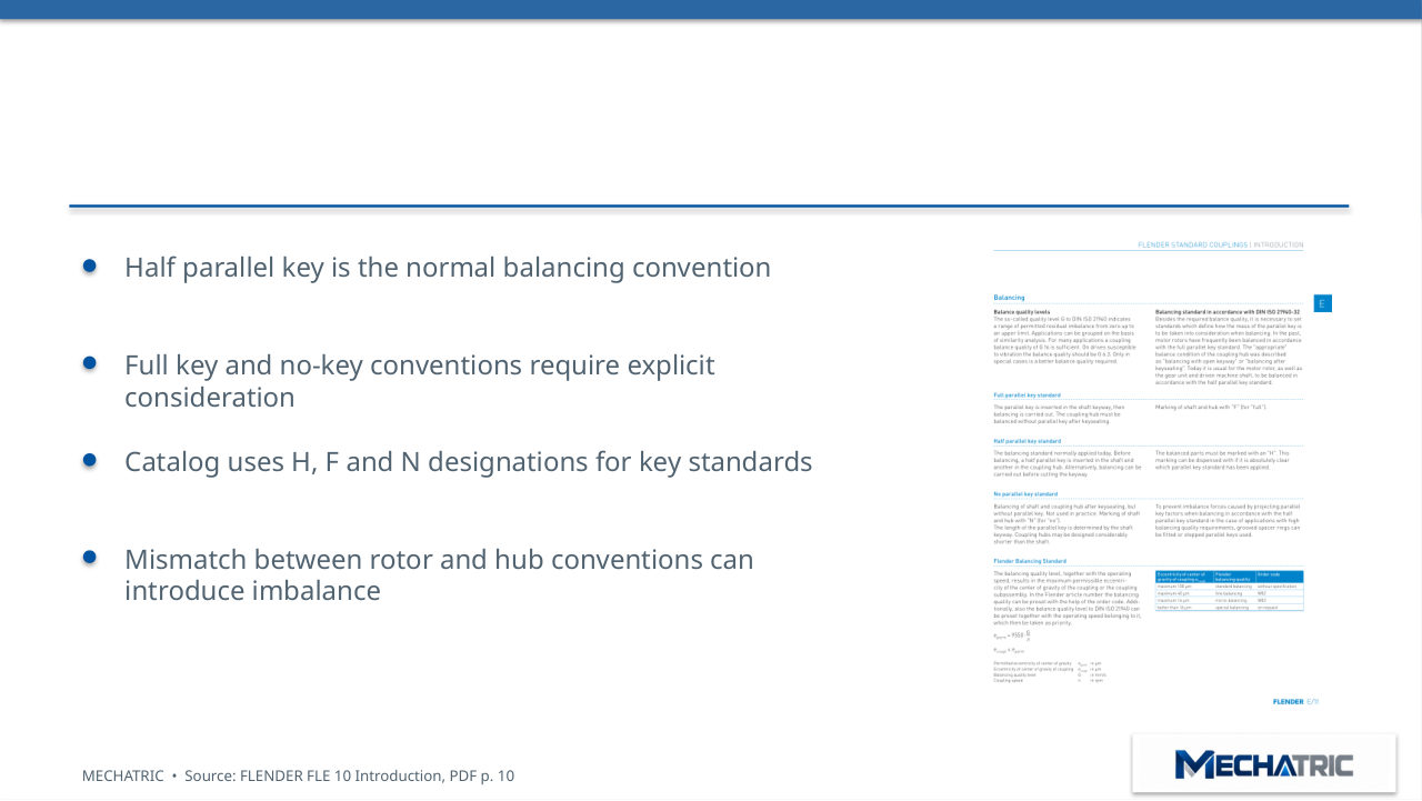
- Half parallel key is the normal balancing convention
- Full key and no-key conventions require explicit
- consideration
- Catalog uses H, F and N designations for key standards
- Mismatch between rotor and hub conventions can
- introduce imbalance
Shaft–hub connections
- Parallel keys and cylindrical finished bores are common
- Alternatives: taper clamping bushes, shrink fits, splines
- Hub torque capability is not automatically equal to
- catalog coupling rating
- Check axial retention, shaft geometry and connection
- stress
Standards and engineering framework
- DIN 740 and VDI 2240 for coupling engineering context
- API 610 / ISO 13709 and API 671 / ISO 10441 appear in
- source references
- DIN ISO 21940 and ISO 21940-32 for balancing/key
- conventions
- Standards cited do not mean every coupling model is
05 – ENGINEERING SELECTION
Selection workflow | Series first
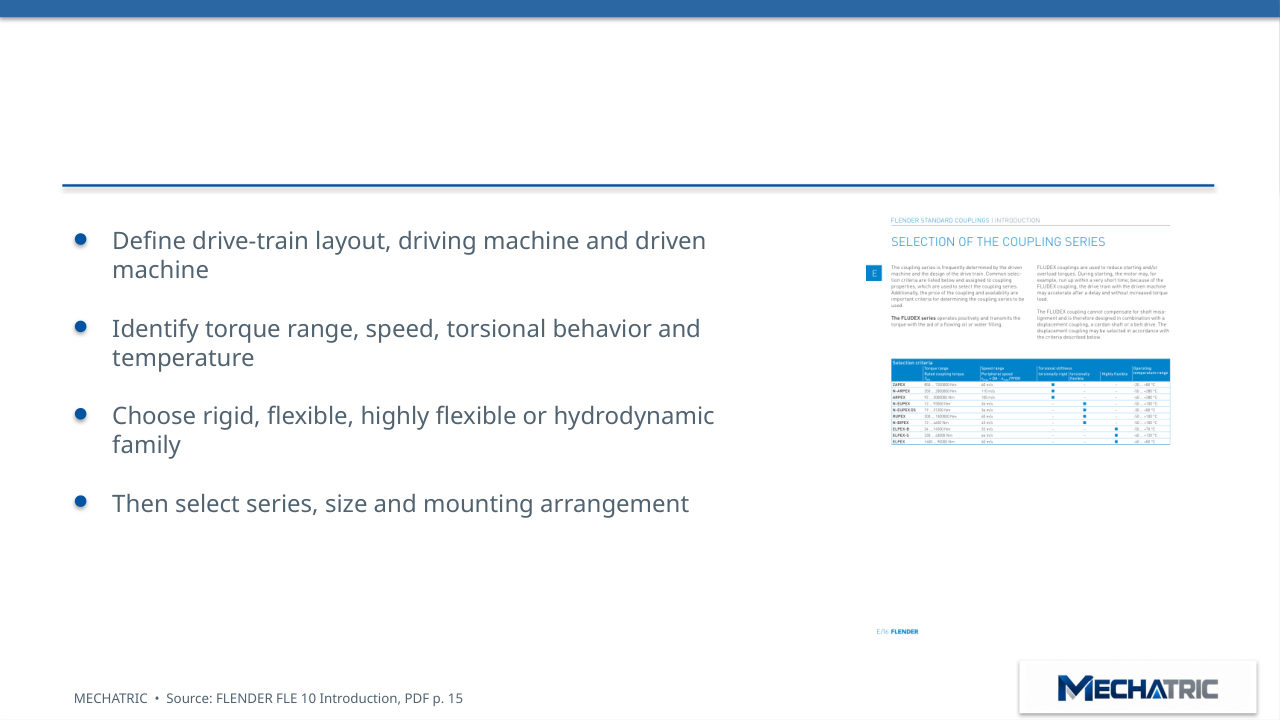
- Define drive-train layout, driving machine and driven
- machine
- Identify torque range, speed, torsional behavior and
- temperature
- Choose rigid, flexible, highly flexible or hydrodynamic
- family
Selection matrix | Torque and speed
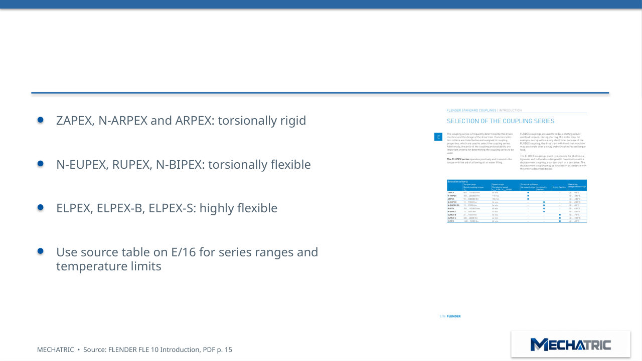
- ZAPEX, N-ARPEX and ARPEX: torsionally rigid
- N-EUPEX, RUPEX, N-BIPEX: torsionally flexible
- ELPEX, ELPEX-B, ELPEX-S: highly flexible
- Use source table on E/16 for series ranges and
- temperature limits
Calculate nominal torque
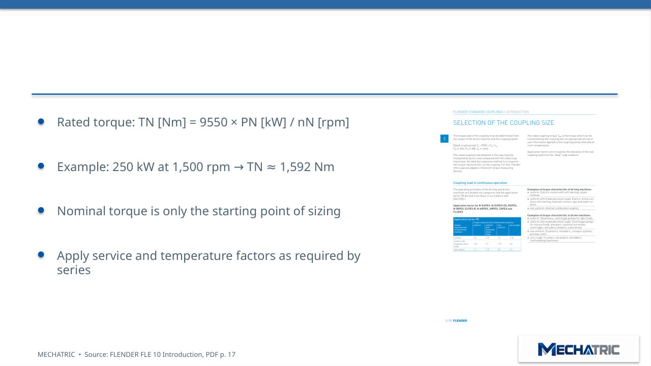
- Rated torque: TN [Nm] = 9550 × PN [kW] / nN [rpm]
- Example: 250 kW at 1,500 rpm
- TN
- 1,592 Nm
- →
- ≈
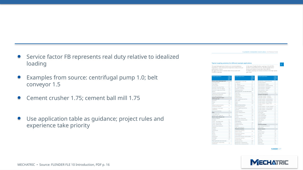
Service factors | Duty matters
- Service factor FB represents real duty relative to idealized
- loading
- Examples from source: centrifugal pump 1.0; belt
- conveyor 1.5
- Cement crusher 1.75; cement ball mill 1.75
- Use application table as guidance; project rules and
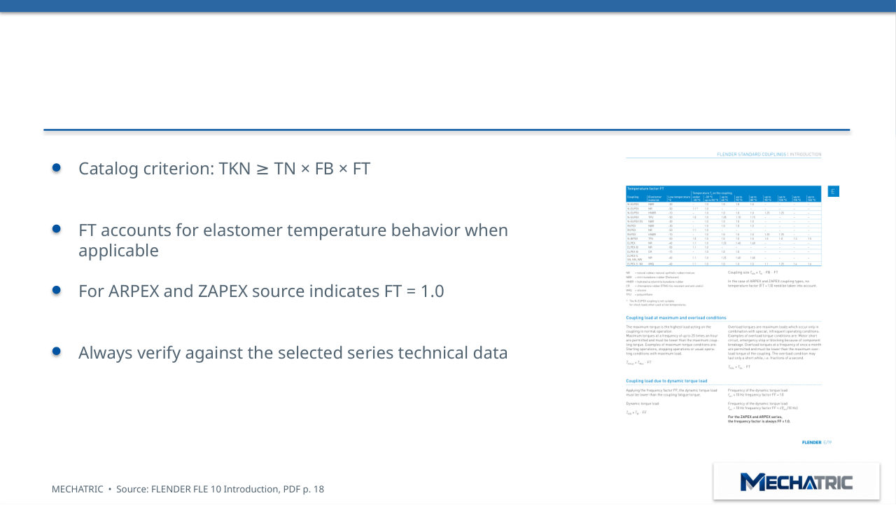
Continuous torque verification
- Catalog criterion: TKN
- TN × FB × FT
- ≥
- FT accounts for elastomer temperature behavior when
- applicable
- For ARPEX and ZAPEX source indicates FT = 1.0
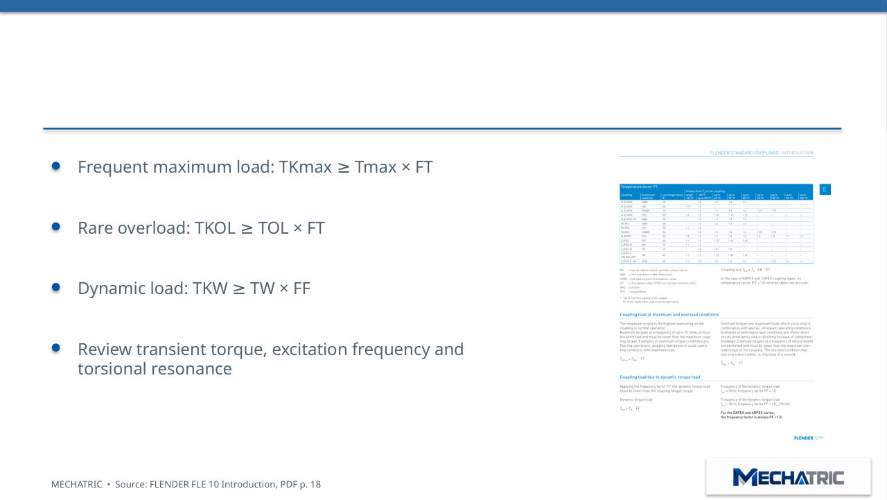
Starting, overload and fatigue checks
- Frequent maximum load: TKmax
- Tmax × FT
- ≥
- Rare overload: TKOL
- TOL × FT
- ≥
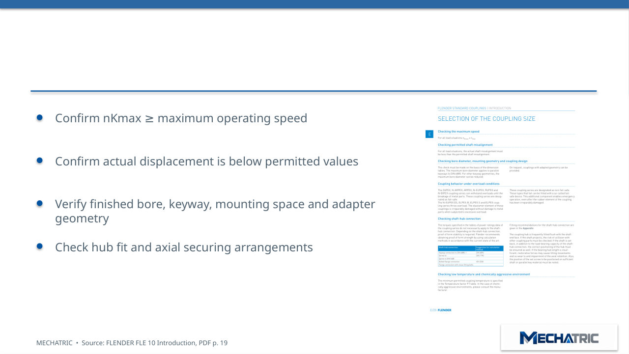
Speed, bore and alignment checks
- Confirm nKmax
- maximum operating speed
- ≥
- Confirm actual displacement is below permitted values
- Verify finished bore, keyway, mounting space and adapter
- geometry
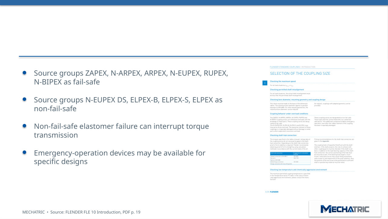
Fail-safe and non-fail-safe behavior
- Source groups ZAPEX, N-ARPEX, ARPEX, N-EUPEX, RUPEX,
- N-BIPEX as fail-safe
- Source groups N-EUPEX DS, ELPEX-B, ELPEX-S, ELPEX as
- non-fail-safe
- Non-fail-safe elastomer failure can interrupt torque
- transmission
06 – APPLICATIONS
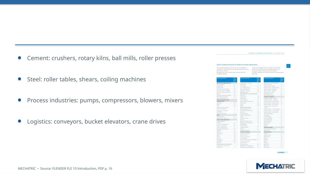
Industrial applications | Selection examples
- Cement: crushers, rotary kilns, ball mills, roller presses
- Steel: roller tables, shears, coiling machines
- Process industries: pumps, compressors, blowers, mixers
- Logistics: conveyors, bucket elevators, crane drives
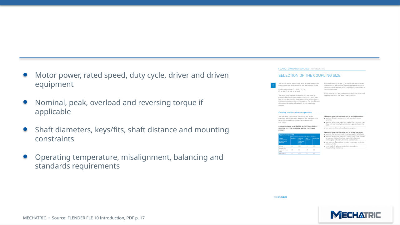
Engineering RFQ | Required inputs
- Motor power, rated speed, duty cycle, driver and driven
- equipment
- Nominal, peak, overload and reversing torque if
- applicable
- Shaft diameters, keys/fits, shaft distance and mounting
- constraints
06 – CONCLUSION
Key takeaways and source reference
- Select the coupling family for torsional and displacement
- behavior
- Verify torque under continuous, peak and dynamic
- conditions
- Check speed, temperature, bore, shaft–hub fit and
- alignment
Need engineering support?
Send your application data and the existing equipment details – MECHATRIC reviews the selection, specification or replacement and prepares the RFQ.
Training material prepared by MECHATRIC from the cited standards and manufacturer documentation. Trademarks belong to their respective owners. Confirm all requirements and ratings against the current editions and manufacturer data for each project.